Operation – Formax Cut-True 27S User Manual
Page 7
16. Paper Alignment Bars
Steel side bar helps to align the paper prior to cutting.
17. Blade Holder
Holds blade in place. There are five screws for blade positioning, (which
should be set up and released step-by-step following the blade replacement
instructions) and adjusting the blade for even operation.
18. Cutting Stick
Plastic stick which protects the edge of the blade during cutting. Can be
repositioned and used on all four sides before being replaced.
19. Cutting Stick Access Slot
Insert screwdriver here in order to lift and remove cutting stick.
20. Stand
Steel stand, assembly required.
21. Side Gauge with Scale
In mm/cm and inches.The indicator on the back-gauge shows the mea-
surement. Fine adjustment is done via the back gauge crank (4). Minimum
adjustment is 0.5mm.
22. Back Gauge
This is moved by rotating the Back Gauge Crank. Used to move the paper
stack into the appropriate cutting position.
23. LED Laser Cutting Line
Shows operator exactly where the blade will cut the paper stack.
24. Blade Adjustment Access
The blade height can be adjusted up to 2mm by using the adjustment screw.
To lower the blade (+), turn to the left. To raise the blade (-), turn to the right.
NOTE: If the blade is adjusted too low, it will cut deeply into the cutting stick,
damaging not only the stick but the cutting blade. The optimal blade height
is when the last sheet in a stack is cut accurately.
Wooden Push Block (not shown)
Used to help align paper stacks for precise cutting.
Blade Change Safety Tool
(not shown)
This device is used to safely remove the blade when it needs to be
sharpened or replaced.
Tool Kit (not shown)
Includes T-wrench and interchangeable bits for use in adjustments and
blade replacement.
1.
Plug in the cutter to an appropriate power outlet.
2.
Turn on the red power switch.
3.
Raise the front safety cover. Slide the paper stack into the cutter along the left edge, using the alignment bar for
guidance. Push it as far back as possible toward the back gauge, without placing hands under the cutting blade.
OPERATION
4
6.
Release the back gauge crank handle by pulling it toward you. This disengages the crank and prevents uninten-
tional movement.
7.
Use the wooden push block to align the front and right edges of the paper stack.
8.
Lower the front safety cover.
9.
Turn the Mode Select Switch key to the right.
10. Press and hold the two clamp engage switches to clamp the paper securely in place. The clamp switches are
indicated by this icon
11.
Press and hold the two blade engage switches to cut the paper. The blade switches are indicated by this icon
After cutting, the blade and clamp will each return to the upright position.
12. Lift the front safety cover and remove the paper stack.
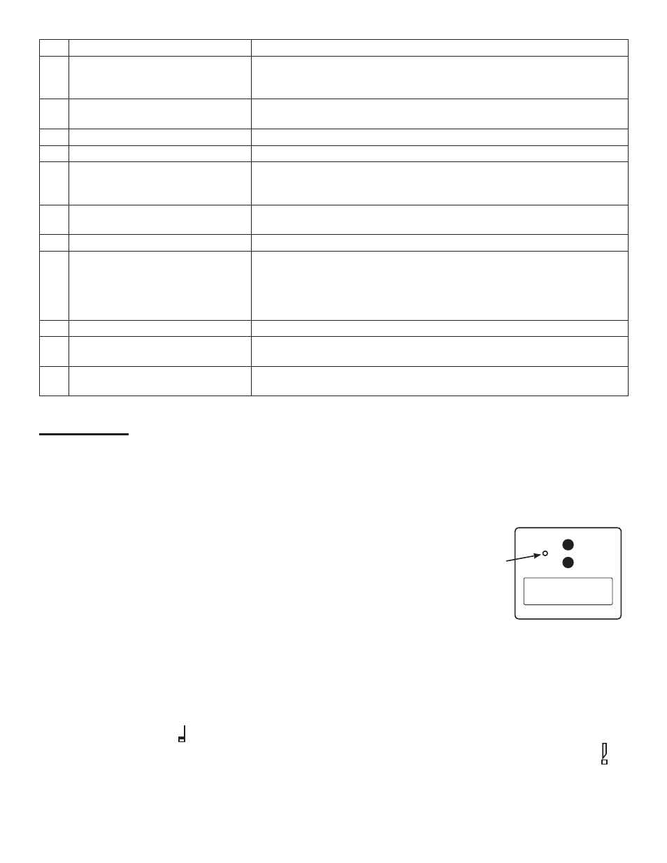
4.
To change the back gauge LED readout between standard and metric, insert
a pin or straightened paper clip into the access hole just above the LED, as
shown in the diagram at right.
5.
Push in the back gauge crank to engage the handle, then turn it clockwise
to bring the back gauge toward the front until the paper is properly matched
with the measurement guide on the side of the machine. The LED digital
readout will indicate the position of the cut. The LED Laser Light will indicate
the position of the blade to help with paper positioning.
inch
cm
1 2 .2 5
Insert pin
here