9 external controls – Fluke Biomedical 190I User Manual
Page 12
Victoreen 1901
Operators Manual
1-8
Voltage Adjustment (RP2)
A +5 volt adjustment is provided on the main circuit board. Refer to Figure 1-2 for adjustment location.
Use the following procedure:
1. Connect the - lead of a DVM to the groundside of R18.
2. Connect the + lead of the DVM to Z10-12.
3. Adjust RP2 for 5.00 V ± 0.02 V.
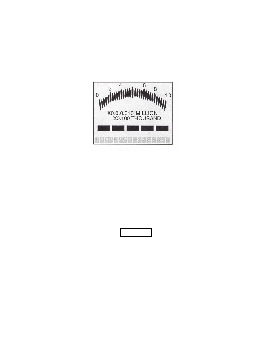
Figure 1-2. 190I Display
1.9 External Controls
The 190I has eight external front panel pushbutton controls. The front panel controls include four
functional buttons and four operational buttons. The functional buttons include including Mode, Log,
Rate/Integ, and Resp Time, effect the daily operation of the unit and are discussed in detail in Section 2, -
Operation.
The four operational pushbuttons and their functions are:
• Light (2) activates the LCD backlight
• Audio toggles the click output on/off and acknowledges an alarm condition
The click output is associated with counting events in the detector.
• On/Off toggles instrument power on/off when allowed by the microprocessor.
The four functional pushbuttons are as follows:
• Mode changes the display units.
• Log, when pushed momentarily, logs currently displayed data or changes current location identifier,
depending on the currently active logging mode; when pressed and held for three seconds, and a
logging with locations mode is active, Log changes the label.
• Rate/Integ toggles the alphanumeric display between the digitized rate value and the integrate
value.
• Resp Time changes the response time on the first range or resets the integrate value and time.
NOTE