Flowserve UNA 14 User Manual
Page 15
15
WINIX
®
2150 is a registered trademark of WINIX GmbH, Norderstedt
Change direction of flow
1. Remove cover I from body B, fig. 3
2. Lever control unit L M N off its support using a screwdriver, fig. 4
3. Turn body so that the arrow A points in the desired flow direction.
4. Position control unit on support and fix it by sharp blows, fig. 5
5. Clean seating surfaces of body and cover.
6. Apply heat-resistant lubricant to seating surface or cover and threads of fixing screws
(use for instance WINIX
®
2150).
7. Insert a new gasket O and put cover onto trap body. Tighten body screws P in diagonally
opposite pairs to a torque of 35 Nm. Retighten screws after the commissioning procedure.
Tools
■
Hexagon-type offset screwdriver (Allen key), size 8 to DIN 911L
■
Screwdriver (5.5/125), DIN 5265
■
Punch (120 /10), DIN 7250
■
Hammer (500 /10), DIN 1041
Heat treatment of welds
A subsequent heat treatment of the welds is not required.
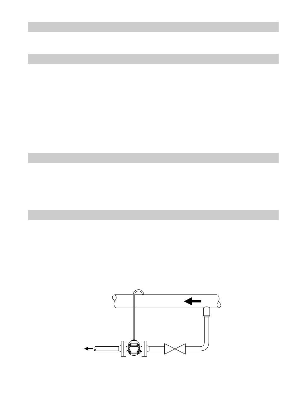
Air balance pipe
For GESTRA air traps UNA 14 P we recommend the installation of an air balance pipe K in order to
equilize the pressure. The air balance pipe ensures a continuous condensate flow from the fluid line
to the trap and effectively prevents the formation of water pockets.
Unfavourable piping geometries and certain positions of installation may also require the installation
of an air balance pipe for steam traps. The air balance pipe effectively prevents the formation of
water pockets.
K