Technical data, Orifices (o) – Flowserve UNA 38 User Manual
Page 6
6
The trap body must not be subjected to sharp increases in pressure. The sizing and dimensional
allowances for corrosion reflect the latest state of technology.
Sizing
Corrosion resistance
When used for its intended purpose, the safe functioning of the steam trap will not be impaired by
corrosion.
Pressure/temperature ratings
For the pressure and temperature ratings, see the designation on the body or the data given on the
name plate.
Explanatory Notes
– continued –
Technical Data
UNA 38, UNA 39
) Observe the pressure/temperature ratings!
)
Inlet pressure minus outlet pressure.
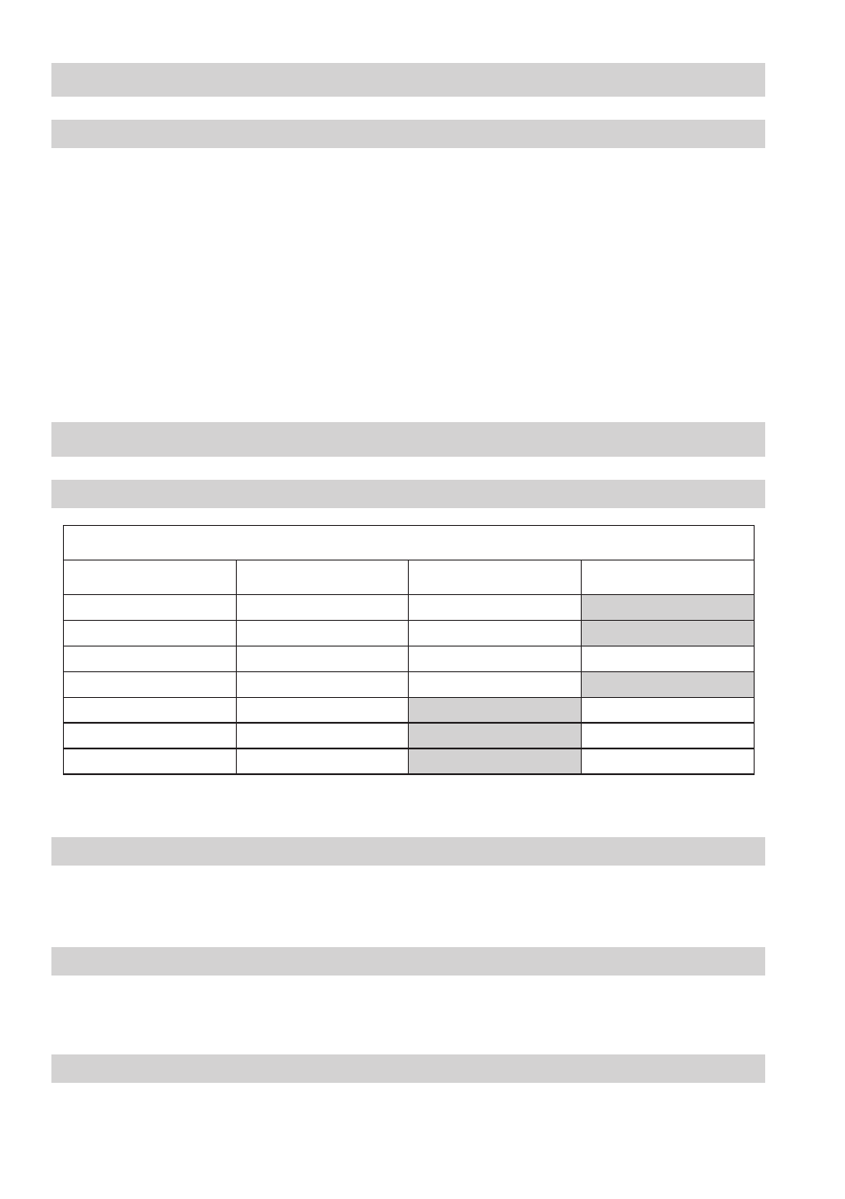
Orifices (O)
Type
∆PMX [bar]
1
)
2
)
UNA 38
UNA 39
O 50
50
X
O 64
64
X
O 80
80
X
X
O 80 MAX
80
X
O 0
0
X
O 40
40
X
O 40 MAX
40
X
Function
– continued –
UNA 38 control unit O 80 MAX and UNA 39 control unit O 140 MAX:
The float ball controls a pilot valve depending on the level of condensate in the trap body. If more
condensate flows through the pilot valve out of the control chamber than follows through a balance
opening, the pressure in the control chamber drops and the bellows of the control chamber is
compressed. The main valve then opens and the condensate is discharged.
The flowing condensate moves the float ball upwards and the pilot valve closes. By means of the vent
hole, the pressure between the control chamber and the interior of the steam trap is evened out, so
that the main valve closes.
The cross-sectional areas of the pilot and main valves are chosen so that only one orifice (O) is needed
for the entire range of differential pressures up to 80 bar (or 40 bar).