Wiring diagram for control unit nrs 1-40.1, Wiring, Fig. 5 – Flowserve NRS1-40.1 User Manual
Page 14
14
– continued –
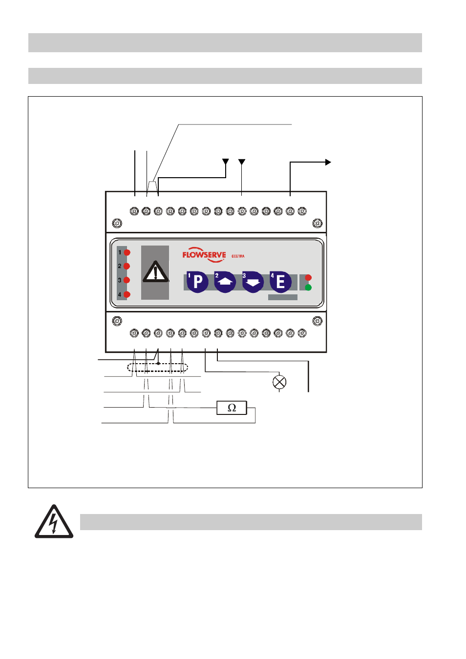
Wiring diagram for control unit NRS 1-40.1
When using the control unit NRS 1-40.1 for more than two limiting functions the CAN bus
must be supplied with 24V DC by a safety power supply unit (e. g. Siemens SITOP Power 05).
The power supply unit must be in accordance with DIN VDE 0106 (safety separation) and
fused with an overcurrent protective device to EN 61010-1 / VDE 0411.
The CAN bus supply must not be connected to terminals 1 and 5.
27
16 17 18 19 20 21 22 23 24 25 26
28 29 30
1
2
3
4
5
6
7
8
9
10 11 12 13 14 15
L
N
N
1
L
H
+
-
C
C
S
Terminating resistor
120
Ω
Fig. 5
S
Wire link with same potential
Safety circuit / supply
Safety circuit - uninterrupted -
L N
MIN
L
N
Further equipment in
the safety circuit
Attention:
NRS 1-40.1 is the
first device in the
safety circuit.
Do not connect termi-
nals 26, 27, 28, 30.
24V DC
Twisted pair cables
Photo-MOS output
24 V-230V AC/ DC, 100mA
Instantaneous alarm signal
Timed malfunction signal
CAN bus
Twisted pair cables
N
L
GESTRA
NRS 1-40
GESTRA
NRS 1-40.1
Attention