Functional elements, Fig.4, Fig. 4) – Flowserve NRS1-40.1 User Manual
Page 12: Fig. 4
12
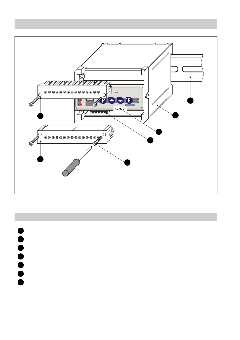
Functional Elements
The code switches are accessible after removing the lower terminal strip. The terminal strips can be un-
plugged after undoing the right and the left fixing screws.
Key
Upper terminal strip
Lower terminal strip
Fixing screws (cross recess head screws M4)
Code switch for setting node ID and baud rate.
Code switch for system configuration
Casing
Supporting rail type TH 35, EN 60715
1
2
3
4
5
6
7
8
9 10 11 12 13 14 15
L
H
+
-
C
C
S
GESTRA
NRS 1-40
GESTRA
NRS 1-40.1
P
1
2
MAX
1
27
16 17 18 19 20 21 22 23 24 25 26
28 29 30
L
N N
1
Te st
E
A
B
C
D
F
G
Fig. 4
A
B
C
D
E
F
G
This manual is related to the following products: