0 wiring of the digital controller, Worcester actuation systems – Flowserve DRC-17 User Manual
Page 7
WCAIM2058
DataFlo Digital Electronic Remote Controller DRC17
7
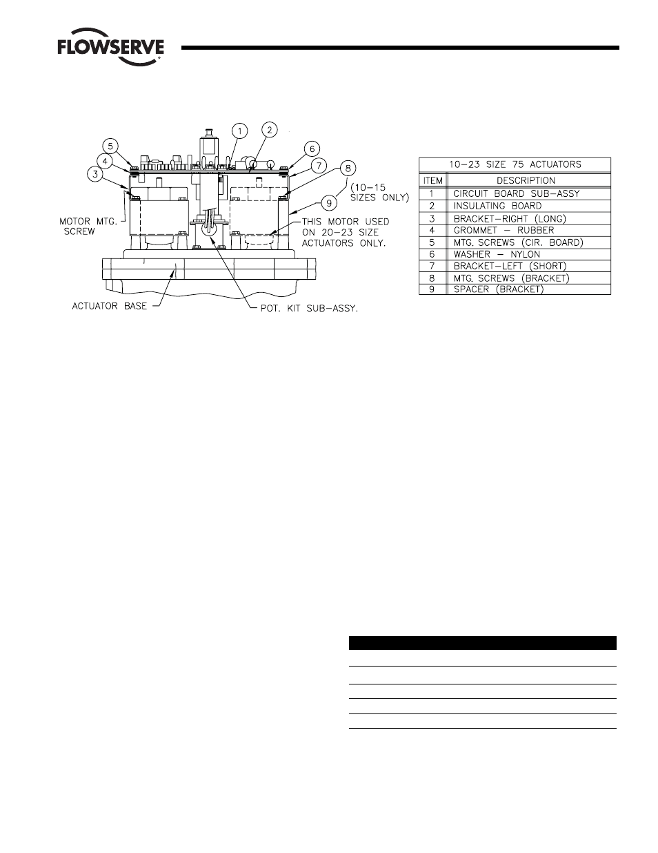
2.3.2 For 120/240 VAC 25 and 30 Size Electric Actuators:
(See Figure 3.)
A. Assemble circuit board to bracket as shown.
B. Place four rubber grommets onto the insulating
board. Put nylon washers on the self-tapping screws
and place screws through the circuit board and
insulating board. Start screws into the bracket.
C. If no insulating board is used, place a rubber
grommet between the board and the bracket. Tighten
all screws such that the grommets are about half
compressed.
D. Use two screws to fasten circuit board bracket to the
motor mounting plate (component side of the board
is facing out).
E. The circuit board is wired to the terminal strip as
shown in Section 3.0.
NOTE: Standard wiring for switches and capacitor as
shown in Figure 3 is the same for 10-23 75 actuators
and is for 120 VAC DRC only. For 240 VAC DRC, see
part 3.1.
2.3.3 Installation of Optional 4-20 Position Output Module
(if used and not factory installed)
A. The output of the position output option is suited for
a 4-20 mA DC meter with 0-100% scale (such as
General Electric type GE185) which is not part of the
package. If properly calibrated, it indicates actuator
shaft position from closed (0°, 0% to open (90°,
100%).
B. The module plugs into the upper left corner of the
Microcontroller Board located in the DRC enclosure.
Align pin 1 (soldered shut) on the module with the
lower right socket on the Microcontroller Board.
3.0 Wiring of the Digital Controller
The DRC consists of three circuit boards: 1) A motor driver board
inside the actuator housing; 2) A power supply board inside the DRC
enclosure; and 3) A microcontroller board inside the DRC enclosure.
The microcontroller board is prewired and installed to the cover of the
DRC enclosure. This wiring procedure discusses wiring for the motor
driver and power supply boards only.
Figure 4 shows the inside of the DRC enclosure. The following wiring
diagrams refer to connectors located inside the DRC enclosure and
the 75 actuator. The DRC enclosure connectors are located as
indicated in Figure 4.
For factory-installed motor driver board, wiring between board,
terminal strip and switches, and for feedback potentiometer has been
done.
Grounding wires should be connected to green colored grounding
screw (if present) on actuator base or to any baseplate mounting
screw in the actuator.
Minimum Fuse Ratings
See table below for minimum fuse rating when overcurrent protection
is used in motor power circuit.
Minimum Fuse Rating for Overcurrent Protection
Actuator Size
Voltage
Fuse Rating
10-23
120 VAC
5 A
25/30
120 VAC
10 A
10-23
240 VAC
3 A
25/30
240 VAC
5 A
NOTE: This table shows the minimum rating to prevent inrush current
from blowing the fuse.
Flow Control
Worcester Actuation Systems
Figure 2