5 modbus function code 03 (read holding register) – Flowserve MX-100 Field Unit User Manual
Page 17
17
MX/DDC-100 Field Unit Installation and Maintenance FCD LMENIM2329-01 – 03/11
flowserve.com
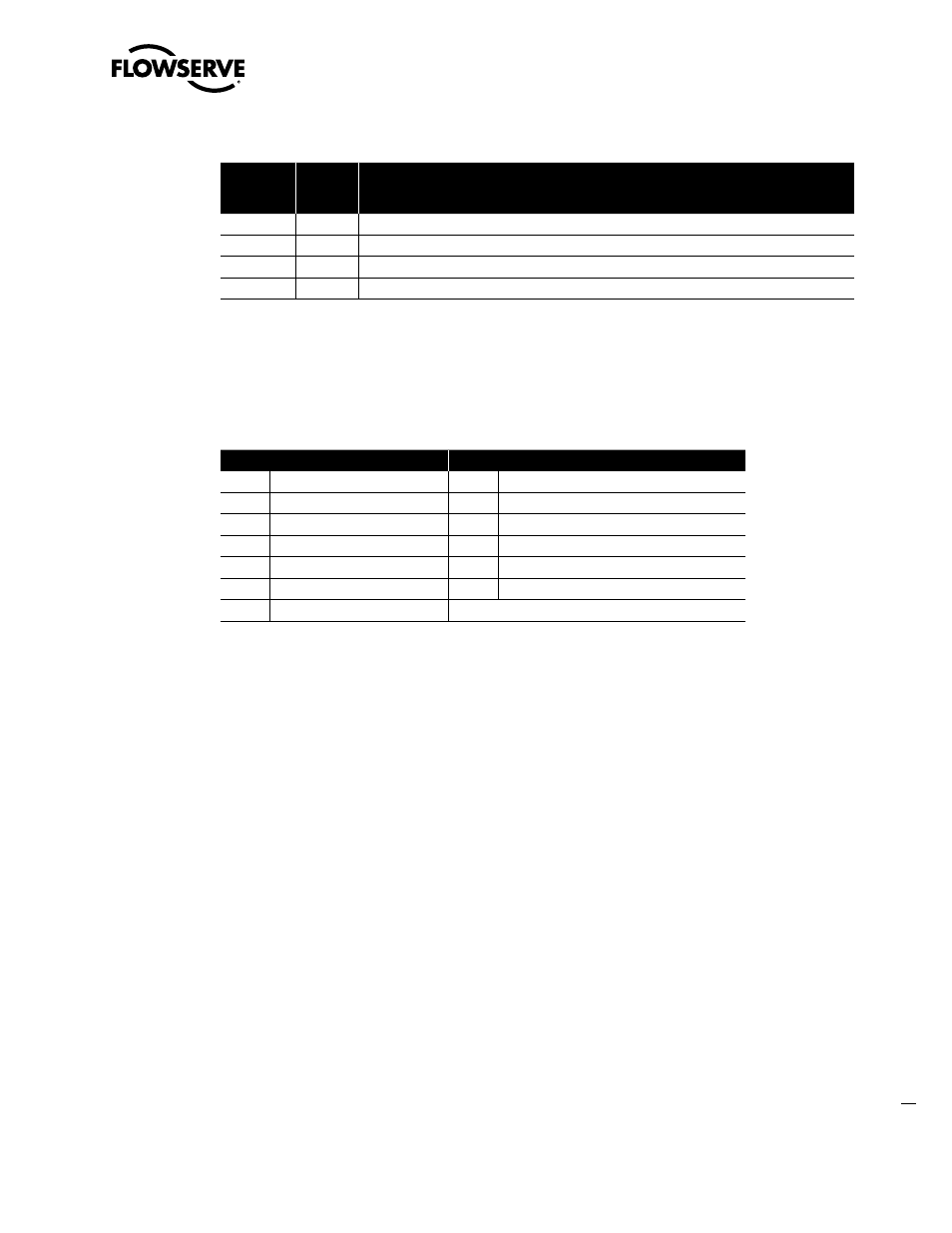
Table 2.3 – Status Bit Definitions (continued)
Bit Number
Modbus
Bit
Address
MX/DDC
205
204
Lost Phase Input
206
205
Phase Reverse Input
207
206
Not used
208
207
PB DP board present
Example
Poll field unit number 22 for 16 inputs starting at input 129 with the actuator opening.
Query: 1602008000107B09
Response: 1602020108CDED
Message Breakdown
Query
Response
16
Slave (Field Unit) Address
16
Slave (Field Unit) Address
02
Function
02
Function
00
Starting Address Hi
02
Byte Count
80
Starting Address Lo
01
1
Data (Inputs 10136 - 10129)
00
No. of Points Hi
08
2
Data (Inputs 10144 - 10137)
10
No. of Points Lo
CDED
Error Check (CRC)
7B09
Error Check (CRC)
Note 1: 01h equals 0000 0001 (actuator open input bit is ON).
Note 2: 08h equals 0000 1000 (actuator Channel B Fail bit is ON).
2.3.5 Modbus Function Code 03 (Read Holding Register)
This function code is used to read the binary contents of holding registers in the DDC-100 Field Unit. This function
code is typically used during the network polling cycle. A network poll should consist of field unit registers 9 (Status)
and 10 (Fault) as a minimum. Holding register 8 should also be polled when the actuator is configured for the analog
feedback option or position control. See Table 2.4 for a complete listing of the holding registers.