Ii. installation, Worcester controls – Flowserve I90 Series User Manual
Page 4
4
Pulsair Loop-Powered Positioner Modular Accessory System (Series I90/L90)
WCAIM2053
II. INSTALLATION
A. MOUNTING INSTRUCTIONS
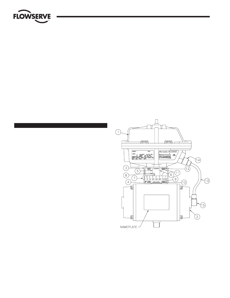
1. Refer to Figure 1. The Series I90/L90 is designed to be
mounted in-line with the major axis of the actuator. The air
connections for the Series I90/L90 should be on the same
end as the air connections for the actuator. The standard 39
actuator has its air connections on the right-hand end cap as
you face the actuator nameplate. The Series I90/L90
nameplate will be on the same side as the actuator nameplate.
2. Ensure that the actuator shaft is in its clockwise position.
Spring-return actuators will be in this position already.
3. Place the mounting bracket on the actuator. Secure the
mounting bracket with the four (4) screws and lockwashers
supplied in the kit.
4. Place the coupling over the actuator shaft. (Note: For the
1039 actuator, shallow slot is placed over the actuator shaft).
The coupling has four (4) threaded holes in it; two are
Z|v-20
thread for set screws; the other two are #10-32 (located 45
degrees off the center line of the coupling) and are not used.
DO NOT tighten the set screws at this time.
5. Place the Series I90/L90 unit on the bracket while inserting the
shaft into the coupling slot. Be certain the holes in the bracket
and I90/L90 housing are aligned and secure with the four (4)
#10-32 socket head screws and lockwashers provided.
6. The coupling set screws can be tightened after the actuator
has been cycled 90 degrees.
Flow Control Division
Worcester Controls
Item No.
Qty.
Description
1
1
Series I90/L90 M.A.S.
2
1
Series 39 Actuator
3
1
Mounting Bracket
4
1
Indicating Scale
5
2
Coupling
6
2
Set Screw
7
1
Indicating Arm
8
1
Locking Nut
9
4
Actuator Mounting Screw
10
4
Actuator Mounting Lockwasher
11
4
M.A.S. Mounting Screw
12
4
M.A.S. Mounting Lockwasher
13
1
Z|v" O.D. X 31" Tubing
(Cut By User)
14
2
Straight Fitting
15
2
Elbow Fitting
Figure 1