Worcester controls – Flowserve I90 Series User Manual
Page 22
22
Pulsair Loop-Powered Positioner Modular Accessory System (Series I90/L90)
WCAIM2053
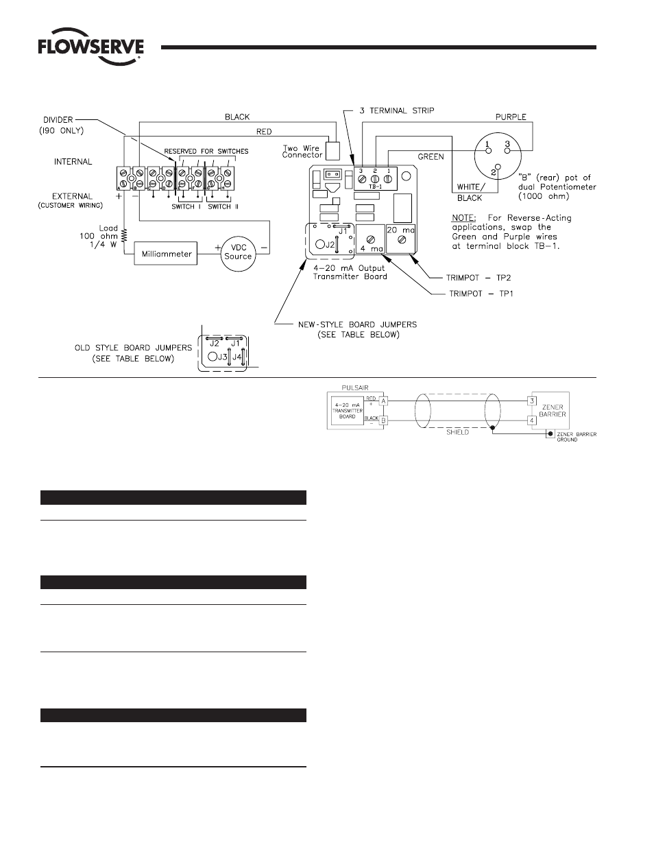
b. Loop Voltage Selection
The jumpers on the circuit board must be set up for the
applied loop driving voltage. As provided, all jumpers will
be installed. See tables below for appropriate jumpers to
be used.
NOTE: Supply voltage must be constant to assure
proper operation.
Old-Style Board Jumpers
Supply
Remove Jumpers
Keep Jumpers
24 VDC
J1 and J3
J2 and J4
12 VDC
J2 and J4
J1 and J3
Intrinsically Safe
J2 and J4
J1 and J3
New-Style Board Jumpers
Supply
Jumpers J1 and J2
24 VDC
Removed
12 VDC
Installed
Intrinsically Safe
Installed
NOTE: For Intrinsically Safe Operation, the circuit must be powered
through a CSA certified zener barrier:
Entity Parameters For I.S. Operation With Barrier
Voltage
≤
30 Volts DC
Current
≤
100 milliamp
Power
≤
1 Watt
IMPORTANT: Shielded cable must be used for each intrinsically safe
circuit and, for zener barriers, the shield must be connected to a
zener barrier ground.
3. CALIBRATION
a. 4-20 mA Output
To adjust the 4-20 mA output of the circuit board connect
the appropriate loop power to the circuit. Connect the
positive lead to terminal A, and the negative to terminal B.
NOTE: The voltage supply loop for the 4-20 mA output
transmitter is independent from the 4-20 mA positioner
input signal loop — they cannot share common wires.
Although the transmitter will operate with no load,
Flowserve recommends using a load of at least 100 ohms
in the current loop.
With the actuator in the full clockwise position, adjust
trimpot TP1 (labeled 4 mA) for a reading of 4 mA on a
milliammeter connected in series with the loop. Once this
adjustment is made, position the actuator to the full
counterclockwise position. Adjust trimpot TP2 (labeled 20
mA) for a reading of 20 mA on the meter. Recheck the 4
mA end of travel and make adjustments as necessary. A
good rule of thumb to follow is that if an adjustment is
made at one end of travel, always go back to the other
end to recheck its adjustment. It should not be necessary
to check each end more than three or four times before
everything is zeroed in.
Flow Control Division
Worcester Controls
-
General Wiring Arrangement