Worcester controls – Flowserve I90 Series User Manual
Page 13
WCAIM2053
Pulsair Loop-Powered Positioner Modular Accessory System (Series I90/L90)
13
8. TROUBLESHOOTING
If the unit does not appear to be functioning properly, then
make the following basic checks.
• Check all wiring to the Positioner board, solenoid valves, and
feedback potentiometer against the wiring diagrams in
Section III.A.7. Also check for broken wires and blown fuses.
• Test the input signal current and check its connections to
the M.A.S. A minimum of 3.6 milliamps is required for the
positioner to operate.
• Check air connections against the information contained in
the Manifold Block Instructions - Section III.C.1. Test the
supply air for pressure and proper connections.
• Rerun the positioner self-calibration procedure outline in
Section III.A.4.c.
NOTE: Many times M.A.S. units are received for repair at
Flowserve and the only problem with the unit is that the
feedback potentiometer is out of calibration. It is very
important that the feedback potentiometer be properly
calibrated for correct operation of the positioner board. It is
also very important that the M.A.S. shaft not be rotated out of
the quadrant for which the feedback potentiometer has been
calibrated. Whenever a problem occurs with positioner
calibration, rerun the positioner self-calibration program
described in section III.A.4.c as a first step.
Problem
Possible Cause(s)
Solution
Unit constantly
Actuator moving
Adjust ramp time
overshoots
too fast
parameter – “tS”
setpoint
No response to
Fuse is blown
Replace fuse
input signal
(L90 only)
(#5X20MM, 63 mA,
fast-acting)
Signal source
Connect good input
connected incorrectly
source as shown on
or no signal
wiring label
As signal increases Potentiometer wires
Check wiring at
actuator suddenly
(green and purple)
terminal strip per
goes full open and reversed
chart below (refer to
will not close
Section III.A.7):
TERM # POT
8
Green
7
White/Black
6
Purple
Actuator
Ramp time parameter
Adjust parameter “tS”
responding slowly
set too high
No response from
Air pressure too low
Pressure should be
piezo valve
40 psig minimum
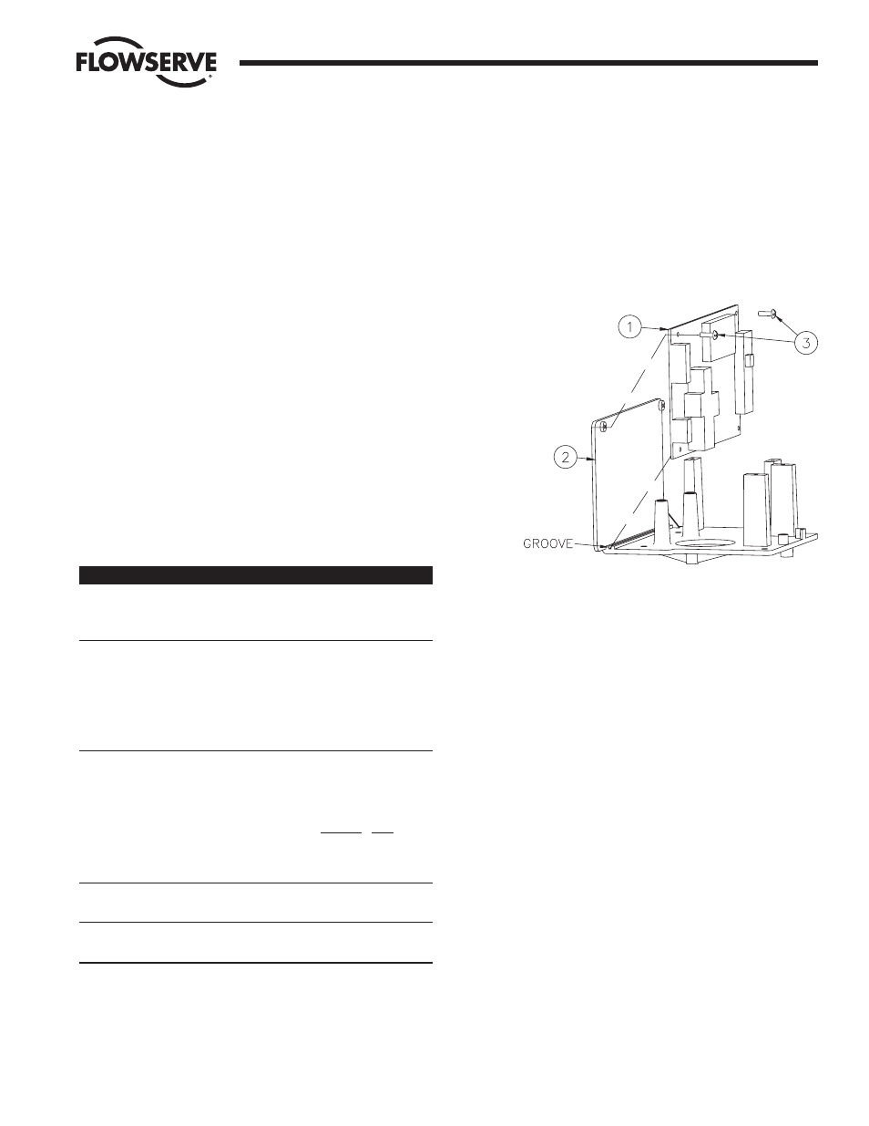
9. CIRCUIT BOARD REPLACEMENT
a. The following information is provided if it becomes
necessary to replace the circuit board.
b. Removing and remounting the positioner circuit board
It may be preferable to wire the new circuit board to the
terminal strip before mounting the circuit board to the
M.A.S. baseplate. This can be done with the baseplate
removed from the housing, if desired. Refer to Figure 7:
1. Turn off the power supply and disconnect the circuit
board (item 1) wires from the terminal strip.
Remove the two #4 screws (item 3) and lift out the
circuit board.
2. Locate the new positioner circuit board (item 1) to the
baseplate (item 2). The bottom edge of the circuit
board fits into a groove in the baseplate as shown.
3. Secure the circuit board with two #4 x
Z|v" self-tapping
screws (item 3) through the top two holes in the
board.
4. Make electrical connections per the wiring diagrams
shown in section III.A.7.
5. Calibrate new board per section III.A.4.
NOTE: All wiring is to be run smoothly and neatly and
away from any rotating parts, using wire ties if necessary.
Use caution to avoid pinching the wires between the base
and cover flanges.
All wiring to terminal strips shall be inserted only to mid-
point of terminal strips.
Flow Control Division
Worcester Controls
Figure 7