Failure analysis – Flowserve MX Electronic Actuator SIL Safety IOM User Manual
Page 34
Limitorque MX Electronic Actuator FCD LMENIM2350-01 – 9/13
34
FLOWSERVE PROPRIETARY INFORMATION
Use or disclosure of this information is subject to the restrictions on the title page of this document
12
Failure Analysis
1. A single failure in MX, DCS or remote wiring of the OPEN or CLOSE signals could cause unexpected actuator
motion if such failure could be interpreted by the MXA as a command signal.
2. If a failure occurs in one of PST or ESD signal paths occurs, then the MXA would not interpret the failed signal as a
command and it would not initiate a PST or ESD action.
3. Using NC and NO contacts at the DCS provides an additional layer of safety by eliminating false commands that
could result from failures in the 24Vdc supply, the remote wiring, the DCS or some failure modes in the MXA input
circuits.
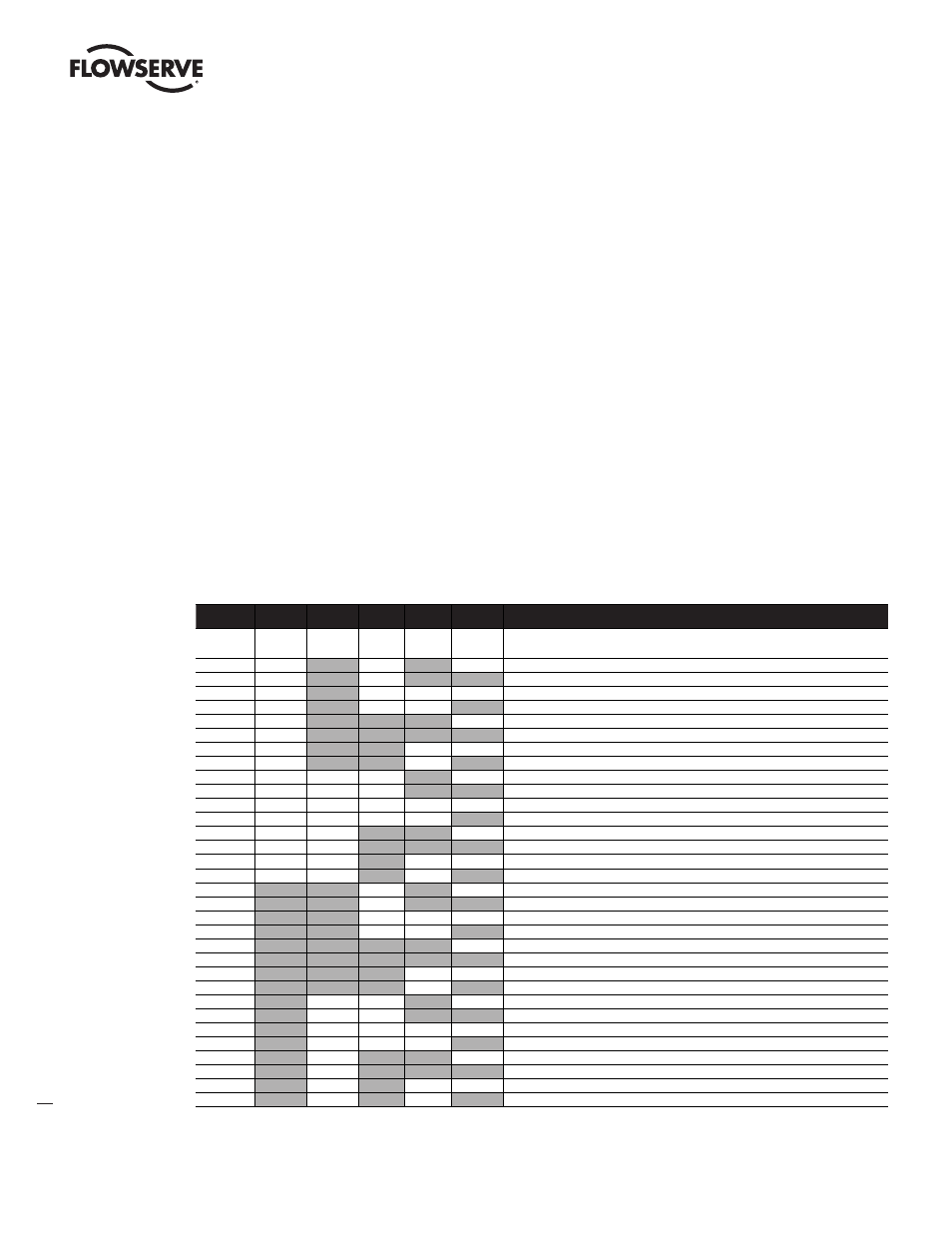
Table 12.1 - Expected Operation for Various Input Signal Combinations
Discrete
Input Signal
ESD
Release 1
ESD Release 2 PST Enable 1 PST Enable 2
ESD/PST
Description
Valid Signal
Assert = 1
Assert = 0
Assert = 1 Assert = 0
Assert = 1
(default)
0
0
0
0
0
Monitor alarm (ESD Release & PST Enable not different => invalid combo)
0
0
0
0
1
ESD Active plus Monitor alarm (ESD Release & PST Enable not different => invalid combo)
0
0
0
1
0
Monitor alarm (ESD Release signals not different => invalid combo)
0
0
0
1
1
ESD Active plus Monitor alarm (ESD Release signals not different => invalid combo)
0
0
1
0
0
Partial stroke enable active plus Monitor alarm (invalid ESD Release signals and PST Enable active)
0
0
1
0
1
Partial stroke active plus Monitor alarm (invalid ESD Release signals and PST Enable active)
0
0
1
1
0
Monitor alarm (ESD Release & PST Enable not different => invalid combo)
0
0
1
1
1
ESD Active plus Monitor alarm (ESD Release & PST Enable not different => invalid combo)
0
1
0
0
0
Monitor alarm ( PST Enable not different => invalid combo)
0
1
0
0
1
ESD Active plus Monitor alarm ( PST Enable not different => invalid combo)
0
1
0
1
0
Do nothing case
0
1
0
1
1
ESD Active
0
1
1
0
0
Partial stroke enable active plus Monitor Alarm (PS enable active)
0
1
1
0
1
Partial stroke enable active, PSESD goes active plus Monitor alarm (PST Enable active)
0
1
1
1
0
Monitor alarm ( PST Enable not different => invalid combo)
0
1
1
1
1
ESD Active plus Monitor alarm ( PST Enable not different => invalid combo)
1
0
0
0
0
ESD Release Active plus Monitor Alarm (PST Enable signals not different => invalid combo)
1
0
0
0
1
ESD Active, ESD Release Active plus Monitor Alarm (PST Enable signals not different => invalid combo)
1
0
0
1
0
ESD Release Active
1
0
0
1
1
ESD Active, ESD Release Active
1
0
1
0
0
ESD Release Active, Partial stroke enable active plus Monitor alarm (PST Enable active)
1
0
1
0
1
Partial stroke active, ESD Release Active, Partial stroke enable active plus Monitor alarm (PST Enable active)
1
0
1
1
0
ESD Release Active plus Monitor Alarm (PST Enable signals not different => invalid combo)
1
0
1
1
1
ESD Active, ESD Release Active plus Monitor Alarm (PST Enable signals not different => invalid combo)
1
1
0
0
0
Monitor alarm (ESD Release & PST Enable not different => invalid combo)
1
1
0
0
1
ESD Active plus Monitor alarm (ESD Release & PST Enable not different => invalid combo)
1
1
0
1
0
Monitor alarm (ESD Release signals not different => invalid combo)
1
1
0
1
1
ESD Active plus Monitor alarm (ESD Release signals not different => invalid combo)
1
1
1
0
0
Partial stroke enable active plus Monitor alarm (invalid ESD Release signals and PST Enable active)
1
1
1
0
1
Partial stroke active plus Monitor alarm (invalid ESD Release signals and PST Enable active)
1
1
1
1
0
Monitor alarm (ESD Release & PST Enable not different => invalid combo)
1
1
1
1
1
ESD Active plus Monitor alarm (ESD Release & PST Enable not different => invalid combo)
NOTE: gray indicates signal asserted
Failure Analysis