Flowserve Marathon-Mach 1 User Manual
Page 7
7
Flow Control Division
Section 1.0
7. On a flat surface place the top cap over the thrust gland.
Thread the adjuster fasteners until snug.
8. The plug stem and diaphragm guide should be checked
for nicks before installing the diaphragm. Nicks on these
surfaces could result in scratches on the lip of the
diaphragm. The diaphragm (Part 5) is assembled over
the plug stem with the aid of the Mach 1 diaphragm
guide, part series #BY86272A (Figure V-A-2).
9. Using the diaphragm guide to protect the o-ring from the
stem edge, install the first o-ring by “rolling” it with your
fingers over the guide and into the lower stem groove
(Figure V-A-3). Install Teflon split ring in a similar manner
such that it is located above the o-ring inside the lower
groove. See Figure V-A-2.
10. Install second o-ring and split ring in upper groove in a
similar manner, except that the diaphragm guide should
be raised by hand so that the lower edge of the guide
does not contact the lower o-ring assembly. Remove the
guide. See Figure V-A-3. Coat both o-ring assemblies
liberally with Krytox
®
grease.
11. Place the thrust gland over the plug stem and gently
maneuver it over the o-rings onto the PFA diaphragm.
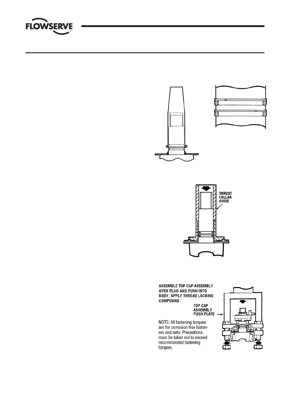
The thrust collar is driven into place through the use of
the thrust collar guide, part series #BY90431A, and an
arbor press (Figure V-A-4a). Press the guide until the
thrust collar bottoms out and then hold for 3 seconds.
Remove the guide.
12. Place the grounding spring (Part 17) over the plug stem.
13. Apply a thin, even coat of silicone on the entire surface
of the 2° plug taper.
14. Place the top cap over the plug stem. Place this
subassembly into the valve body. Align top cap anti-
rotation lugs with the stops in the body. Using an arbor
press or c-clamp, push down on the top cap evenly until
the top cap gasket pad seats firmly against the body
counterbore. When pressing make sure the top cap does
not bind with the stops. It is also very important not to
press with the plug stem. Use part series AY97223A to
push the top cap while clearing the plug stem (Figure
V-A-4b). Apply thread locking compound to the threads
of the top cap fasteners. Tighten the top cap fasteners to
the torque values found in Torque Tables V-A-II, V-A-III
and V-A-IV.
15. Remove the valve from the arbor press, loosen the
adjuster fasteners, and operate the plug several times. It
will turn hard at first but will then loosen and turn freely.
SECTION V
FIGURE V-A-2
FIGURE V-A-3
FIGURE V-A-4a
FIGURE V-A-4b