Flowserve Marathon-Mach 1 User Manual
Page 4
4
Flow Control Division
Section 1.0
10. For Marathon valves, be sure to remove the o-rings and
backup rings first and then the PFA diaphram.
11. Inspect the valve port seals or sleeve for wear or damage,
especially scratches near the top, bottom, and port areas.
If wear or damage is excessive, the port seals/sleeve
should be replaced.
12. Remove port seals or sleeve as follows:
NOTE: Care must be taken not to damage the machined
internal body bore.
a. Lift port seals out of body bowl.
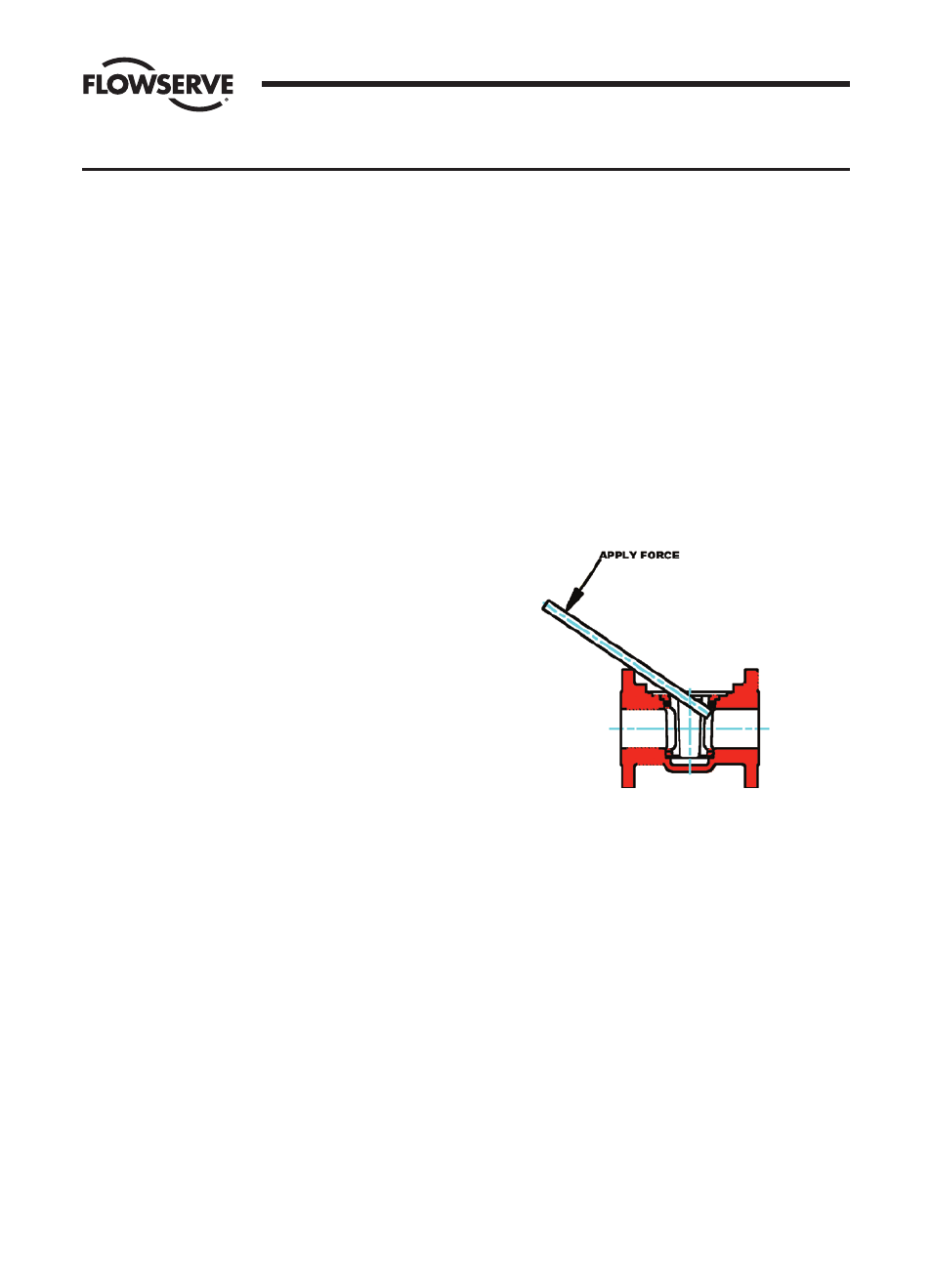
b. To remove the sleeve, use a wooden dowel and pry the
sleeve upward by engaging the dowel in the sleeve at
the top of the port. A sharp blow may be necessary to
dislodge the sleeve. Both sides of the sleeve may need
to be pried upward for removal. (See Figure III-1)
FIGURE III-1
13. Thoroughly clean all valve parts with an acceptable
cleaner.
14. Inspect parts for damage. Look for marred, scratched,
or rough sealing surfaces on the valve plug or machined
body bore.
NOTE: Reinstallation of damaged or unclean parts will
ruin any replacement seals installed into the valve.
RECOMMENDED PRECAUTIONARY MEASURES
1. Valves must be relieved of process fluid and pressure
prior to disassembly.
2. Personnel performing disassembly must be suitably
protected and alert for emission of hazardous
process fluid.
DISASSEMBLY STEPS
NOTE: Refer to Figure II-1 for parts identification. If an actua-
tor or gearbox operates the valve, alignment marks should be
noted to assure correct orientation when reassembled. This
may best be accomplished by making matching marks on the
plug stem and operator housing with no burrs made on the
plug stem.
1. Remove the wrench (Part 16), if so equipped. Remove the
stop collar retainer (Part 15), stop collar (Part 14) and
locking stop (Part 12) after marking their orientation.
2. Gradually loosen adjuster fasteners (Part 11) - DO NOT
REMOVE.
3. WARNING: Do not loosen or remove top cap fasteners
(Part 10) when removing an operator. Remove the
operator by unfastening it from the bracket.
4. Turn plug (Part 4) in order to raise the plug to vent any
material trapped in the valve (see note below).
NOTE: If there is no upward movement of the plug,
it will be necessary to devise a method of lifting the plug
upward. This may require removal of the valve operator
(Step 3). This operation should be undertaken noting the
above precautionary measures. Methods of plug removal
must include protective measures on plug stem and
plug end.
5. Once the plug has lifted, the adjuster fasteners (Part 11)
can be completely removed.
6. Gradually loosen but DO NOT REMOVE all of the top cap
fasteners (Part 10). Turn the plug until it is loose from
the port seal (Part 2) or sleeve (Part 3) and all pressure
has been vented. (Again, it may be necessary to use a
mechanical means to move the plug upwards.)
7. Remove the top cap fasteners and top cap (Part 9) from
the plug stem. Retain the tags for attachment during
re-assembly.
8. Remove the plug (Part 4) from the body (Part 1).
9. Remove the grounding spring (Part 8) and thrust gland
(Part 7).
SECTION III
VALVE DISASSEMBLY - MARATHON-MACH 1