Flowserve G4 Sleeveline Plug Valves User Manual
Page 9
9
G4, G4ZHF AND G4R USER INSTRUCTIONS ENGLISH 5-14
Due to the tooling and associated equipment required
(presses, fixtures, etc.) to rebuild 10"–14" size valves, it is highly
recommended they be returned to the factory or a Flowserve
Authorized Black Tie Valve Rebuilder for repair and rebuild.
Many valves made by Flowserve Corporation handle corrosive
chemicals which may be injurious to property or personnel.
Valves returned without proper attention given to the safety
requirements will be shipped back to the consignor collect.
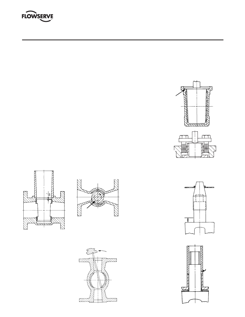
NOTE: Part number reference is shown in Figure V B-7.
1. Apply Durco seal 1028B to the inside of the tapered bore
in the body and permit to dry before assembly. RAD-1
material is used for nuclear applications.
2. Apply a light coating of oil or silicone to the interior of the
coining die or to the O.D. of the sleeve. Position the sleeve
in the coining die, part series #BY79542A, so that the
diagonal opposite sides of the sleeve port will lock behind
the metal lips in the body (Figure V B-2). The sleeve is then
pushed directly through the coining die into the valve body
until the sleeve drops below the top counterbore of the
valve body (Figure V B-1).
SECTION V
B. VALVE ASSEMBLY – 1"–8" G4, G4R
Push sleeve directly through coining
die until sleeve drops below top
counterbore of the valve body.
A special plug with retractable
or removable blades engages
the two remaining sleeve ports
and pulls them until they fall
behind the body port lips.
FIGURE V B-2A
Optional assembly operation
for 1" & 1
1
⁄
2
" G-4 valves
Care must be exercised to
ensure that the bar does not slip
and gouge or tear the sleeve.
DIRECTION OF
ROTARY MOTION
FIGURE V B-1
FIGURE V B-2
3. A special plug, part series
#BY79664A, containing
retractable or removable
blades is lowered into
the body with the blades
re tracted or removed. The
blades are then installed or
extended and a counter-
clockwise rotary motion is
applied to the plug engaging
the two remaining diagonal
oppo site sleeve port open-
ings and pulling them until
they fall behind the body port
lips. The plug is then ro tated back to its original position,
and the blades are then removed or retracted. The plug is
then removed from the body (Figure V B-2). In the 1" and
1
1
/
2
" sizes, a bar may be substituted for the locking plug.
See Figure V B-2A for a description of this operation.
4. Apply a thin film of oil on
the sizing plug, part series
#BY79555A, and push it into
the sleeve until the sizing
plug flange bottoms against
the counterbore of the valve
body (Figure V B-3). Allow
the sizing plug to remain in
this position for one minute.
5. Place the top cap (Part 3)
and adjuster (Part 12) over
the thrust collar. The adjuster
fasten ers should be threaded
into the top cap until flush
with the bottom (Figure
V B-4).
6. The diaphragm (Part 6) is
as sembled over the plug
stem with the aid of the G4
diaphragm guide, part series
#BY77543A (Figure V B-5)
and #BY79581A. The plug
stem and diaphragm guide
should be checked for nicks
before installing the dia-
phragm. Nicks on these
surfaces could result in
scratches on the lip of the
dia phragm.
7. The thrust collar is then
assembled over the plug
stem and driven into place
through the use of the thrust
collar guide, part series
#BY77545A, and an arbor
press (Figure V B-6).
FIGURE V B-3
The sizing plug is pushed
into the sleeve until the
sizing plug flange bottoms
against the counterbore of
the valve body.
FIGURE V B-5
If damaged, the plug taper and
1/2" in length of stem must be
repolished to a surface finish
of 16AA on the taper and stem.
1
/
2
"
THRUST
COLLAR
GUIDE
FIGURE V B-4
Thrust collar to be flush with
gasket surface of top cap.
FIGURE V B-6
9