Warning – Flowserve G4 Sleeveline Plug Valves User Manual
Page 3
3
G4, G4ZHF AND G4R USER INSTRUCTIONS ENGLISH 5-14
SECTION II
OPERATING/MAINTENANCE INSTRUCTIONS FOR G4, G4ZHF, G4R
Maintenance requirements for G4, G4ZHF and G4R valves
may vary due to operating conditions of the process. Factors
such as operating temperature, pressure, solids content, and
frequency of cycling can influence valve performance and
maintenance requirements.
Seal wear is compensated by adjusting appropriate parts. For
G4, G4ZHF and G4R valves, there are three possible leak paths:
1. Top Cap (bonnet)
2. Stem
3. Line (through)
Corresponding adjustments for each leak path are as follows:
NOTE: Refer to Figure II-1 or Figure VI-1A for parts identification.
1. Top Cap (bonnet)
Leakage due to thermal or pressure cycling is eliminated
by snugging the top cap fasteners (Part 3A) in a “criss-
cross" pattern. This adjustment is most effective when the
valve is not pressurized. It is important that the top cap
fasteners not be tightened excessively and that torque
values applied be within industry standard for fasteners.
2. Stem
Leakage due to wear of the diaphragm, and/or wear to
the sleeve (primary seal) is eliminated by tightening the
adjuster fasteners (Part 12A) in
1
/
4
turn increments. It is
recommended that the adjuster fasteners be tightened
evenly.
The valve should be operated between adjustments to
assure that the plug properly seats itself into the sleeve.
If leakage persists after repeated adjustments, the sleeve
and diaphragm will require replacement, as covered in
Section V A and V B or Section VI.
3. Line (through)
Through leakage due to wear of the primary seal can be
eliminated by tightening the adjuster fasteners (Part 12A)
in
1
/
4
turn increments. It is recommended that the
fasteners be tightened evenly.
The valve should be operated during adjustments to pre-
vent excessive operating torque. Should leakage persist
after repeated adjustments, the sleeve will require replace-
ment, as covered in Section V A and V B or Section VI.
WARNING
To avoid personal injury and prevent damage to
equipment, do not operate or repair this valve without
observing the following procedures outlined in this
manual.
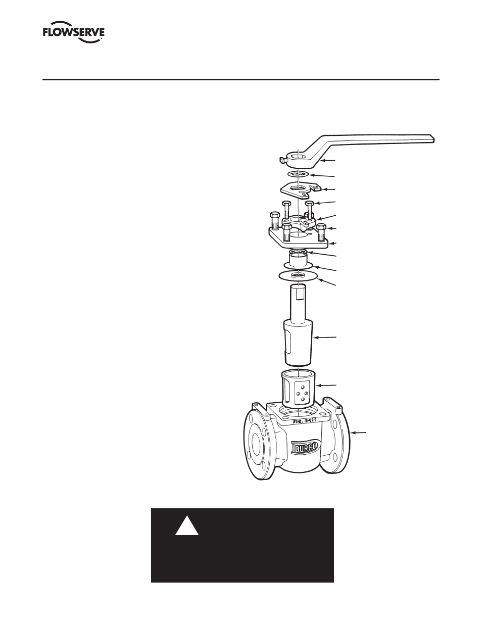
FIGURE II-1
TYPICAL ASSEMBLY OF G4 AND G4R VALVE
!
WRENCH (13)
STOP COLLAR RETAINER (19A)
STOP COLLAR (19)
ADJUSTER FASTENERS (12A)
ADJUSTER (12)
TOP CAP FASTENERS (3A)
TOP CAP (3)
GROUNDING SPRING (17)
THRUST COLLAR (11)
DIAPHRAGM (6)
PLUG (2)
SLEEVE (5)
BODY (1)