G4, g4r – Flowserve G4 Sleeveline Plug Valves User Manual
Page 7
7
G4, G4ZHF AND G4R USER INSTRUCTIONS ENGLISH 5-14
1. Apply Durco
®
seal 1028B to the inside of the tapered bore
in the body and permit to dry before assembly. RAD-1
material is used for nuclear applications.
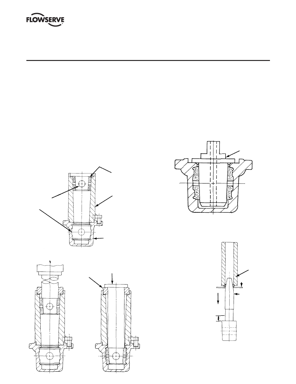
2. Assemble sleeve into body with a coining die, part
#BY81917A. Position coining die so locating pins are
located in bonnet flange holes in body. Position sleeve in
coining die so that sleeve holes are centered over body
ports (Figure V A-1). Place push rod and push rod guide in
coining die and push sleeve into body until push rod stops
on push rod guide (Figure V A-2).
3. Size sleeve. Check sleeve in body to make sure sleeve vent
holes are still centered between body ports. Apply a light
coat of silicone lubricant to sizing Plug #1 and siz ing Plug
#2, part #BY80017B & C. Push sizing Plug #1 into sleeve
until the sizing plug flange bottoms against the counter-
bore of the valve body. Remove #1 sizing plug and now
push #2 sizing plug in the same manner, but HOLD SIZING
PLUG IN PLACE for 15 SECONDS (Figure V A-3).
1. Rough Size With Plug #1
2. Finish Size With Plug #2 (Hold for 15 Seconds)
4. The plug stem and
dia phragm guide are to
be checked for nicks or
burrs before installing
the dia phragm. Nicks
on these surfaces could
result in scratches on
the lip of the dia phragm.
Assemble diaphragm
over plug stem with the
aid of the diaphragm
guide, part #BY77543A,
and assembly tool,
part #BY80019A.
(Figure V A-4).
5. Preassemble the top cap
and adjuster, ad just ing
the cap screws so that
the bottom of the thrust
collar is flush with the
bottom face of the top
cap (Figure V A-5).
SECTION V
A. VALVE ASSEMBLY –
1
/
2
" &
3
/
4
" G4, G4R
PUSH ROD
GUIDE
PUSH ROD
SLEEVE HOLE
CENTERED
OVER BODY
HOLE
VALVE BODY
COINING DIE
PTFE SLEEVE
FIGURE V A-1
ASSEMBLE SLEEVE
FIGURE V A-2
PUSH SLEEVE IN BODY
SIZING PLUG
FIGURE V A-3
SIZE SLEEVE
Valve assembly will require usage of a repair tooling kit
that is specific to the size of the valve. These kits can be
obtained from Flowserve FCD, Cookeville, Tenn.
FIGURE V A-4
DIAPHRAGM
ASSEMBLY
TOOL
DIAPHRAGM
DIAPHRAGM
GUIDE
ASSEMBLE DIAPHRAGM
ON PLUG
If damaged the
plug taper and 1/2"
in length of stem
must be repolished
to a surface finish
of 16AA on the
taper and stem.
1
/
2
"