Maximum differential pressures – Flowserve BX2001 Durco User Manual
Page 32
DURCO BX2001 USER INSTRUCTIONS ENGLISH 9-13
32
SECTION XIV
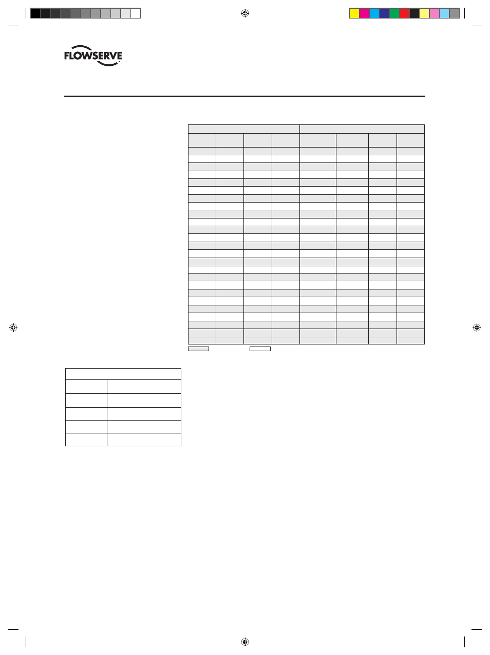
BX2001 FLANGE DRILLING SPECIFICATIONS — Fastener Thread Sizes
Big Max high performance butterfly valves
meet the following flange
specifications:
ASME B16.5
2 in (50 mm) -
24 in (600 mm)
MSS SP44
30 in (750 mm) &
36 in (900 mm)
ASME B16.47
30 in (750 mm) &
(Series A)
36 in (900 mm)
Maximum Differential Pressures
Valve Size
Max ∆P –
in (mm)
Valve 90° open†
3
34 PSIG
(80)
(2.3 bar)
4
16 PSIG
(100)
(1.1 bar)
6
7 PSIG
(150)
(.5 bar)
8
5 PSIG
(200)
(.3 bar)
†Based on a 120 pound maximum force on wrench.
See MSS SP91 for further clarification.
* The two fastener holes on either side of the shaft, top and bottom, are tapped blind holes (both sides).
** Four fastener holes, two on either side of the shaft top and bottom, are tapped blind holes, both sides.
*** The two fastener holes on either side of the shaft, top and bottom, are tapped through.
Wafer Style – Class 150 and 300 Drilling Lug Style – Class 150 and 300 Drilling
Size
No. of
Hole Size
B.C.
No. of
Thread Size
B.C
B1
in (mm)
Holes
Inch
in (mm)
Fasteners
Inch
in (mm)
in (mm)
2 (50)
4
3
/
4
4
3
/
4
(121) 4
5
/
8
-11 4
3
/
4
(121)
6 (152)
2 (50)
2
3
/
4
5 (127)
8
5
/
8
-11
5 (127)
6
1
/
4
(154)
3 (80)
2
3
/
4
6 (152)
4
5
/
8
-11
6 (152)
7
1
/
2
(191)
3 (80)
2
7
/
8
6
5
/
8
(168)
8
3
/
4
-10 6
5
/
8
(168) 8
1
/
8
(206)
4 (100)
2
3
/
4
7
1
/
2
(191) 8
5
/
8
-11 7
1
/
2
(191)
9 (229)
4 (100)
2
7
/
8
7
7
/
8
(200) 8
3
/
4
-10 7
7
/
8
(200) 9
3
/
8
(238)
6 (150)
2
7
/
8
9
1
/
2
(241) 8
3
/
4
-10 9
1
/
2
(241)
11 (279)
6 (150)
2
7
/
8
10
5
/
8
(270) 12
3
/
4
-10 10
5
/
8
(270) 12
1
/
8
(308)
8 (200)
2
7
/
8
11
3
/
4
(298) 8
3
/
4
-10 11
3
/
4
(298) 13
1
/
2
(343)
8 (200)
2
1
13 (330)
12
7
/
8
-9 13
(330) 14
3
/
4
(315)
10 (250)
2
1
14
1
/
4
(362) 12
7
/
8
-9 14
1
/
4
(362)
16 (406)
10 (250)
4***
1
15
1
/
4
(387) 16
1-8 15
1
/
4
(387) 17
1
/
4
(438)
12 (300)
2
1
17 (432)
12
7
/
8
-9
17 (432)
19 (483)
12 (300)
4***
1
1
/
8
17
3
/
4
(451) 16
1
1
/
8
-8 17
3
/
4
(451) 20
1
/
4
(514)
14 (350)
4
1
1
/
16
18
3
/
4
(476) 12
1-8 18
3
/
4
(476)
21 (533)
14 (350)
8*
1
1
/
8
20
1
/
4
(514) 20*
1
1
/
8
-8 20
1
/
4
(514)
23 (584)
16 (400)
4
1
1
/
16
21
1
/
4
(540) 16
1-8 21
1
/
4
(540) 23
1
/
2
(597)
16 (400)
8*
1
1
/
4
22
1
/
2
(572) 20*
1
1
/
4
-8 22
1
/
2
(572) 25
1
/
2
(648)
18 (450)
4
1
3
/
16
22
3
/
4
(578) 16
1
1
/
8
-8 22
3
/
4
(578)
25 (635)
18 (450)
8*
1
1
/
4
24
3
/
4
(628) 24*
1
1
/
4
-8 24
3
/
4
(628)
28 (711)
20 (500)
8*
1
1
/
8
25 (635)
20*
1
1
/
8
-8
25 (635)
27
1
/
2
(699)
20 (500)
10*
1
1
/
4
27 (686)
24*
1
1
/
4
-8
27 (686)
30
(762)
24 (600)
8*
1
1
/
4
29
1
/
2
(749) 20*
1
1
/
4
-8 29
1
/
2
(749)
32 (813)
30 (750)
16*
1
1
/
4
36 (914)
28**
1
1
/
4
-8
36 (914)
38
3
/
4
(984)
36 (900)
16**
1
1
/
2
42
3
/
4
(1086) 32**
1
1
/
2
-8 42
3
/
4
(1086) 46 (1168)
All dimensions are approximate and for illustration purposes only. For exact dimensions request certified dimensional prints.
ASME Class 150
ASME Class 300
Due to the hydrodynamic
torque encountered with
butterfly valves, safe operating
practices dictate that manual
gear operators, pneumatic
actuators or electric actuators
be used when these differen-
tial pressures are exceeded.
(DVENIM0390-02)-BX2001_update.indd 32
10/10/13 2:08 PM