Flowserve BX2001 Durco User Manual
Page 23
DURCO BX2001 USER INSTRUCTIONS ENGLISH 9-13
23
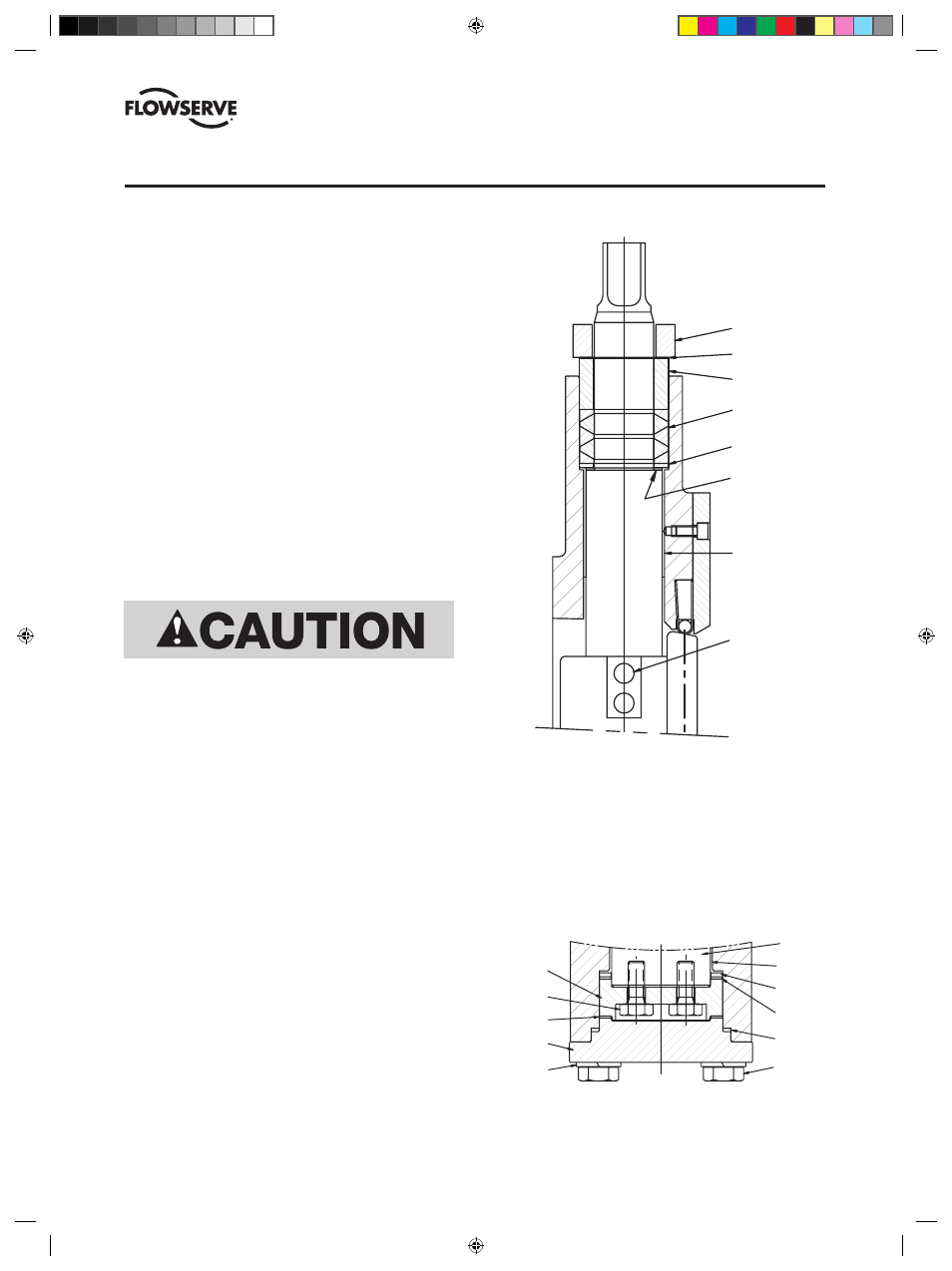
10. For valves with bottom end cap design, slide one thrust
bearing onto the shaft, attach the bearing cap to the end
of the shaft (use thread cement and torque fasteners to
30 ft-lbs). Place the second thrust bearing on the bearing
cap. Place the bottom cap gasket on the bottom cap and
install the bottom cap. Torque bottom cap fasteners to
75 ft-lbs in a criss-cross pattern.
SECTION VII
COMPLETE VALVE REPAIR (continued)
vALvE ASSEMBLY — 14" thru 36"
1. Lay the valve body on the table with the seat pocket side
down. Insert a bearing into the top and bottom shaft
bore. Some designs of fire sealed bearings require a
separate metal outer sleeve (included in the repair kit).
Insert the PTFE/stainless bearing into the metal sleeve
prior to installing the bearing into the shaft bore. Note:
Severe service and fire sealed bearings are split. Align
the splits towards opposite sides of the valve.
2. Insert packing thrust washer, packing set and packing
gland into the top packing bore of the valve body. Install
packing adjuster and fasteners. Finger-tighten the
fasteners. These fasteners will be tightened to the
required torque after the shaft is installed. Do not install
the bottom packing set. It is installed after the shaft.
3. Place the disc face down into the valve body with the disc
pin holes towards the top of the body. Align the shaft
bores of the disc and valve body. Very close alignment
of the bores is required to insert the shaft.
4. Carefully slide the shaft through the bottom shaft bore
(the end without the stem packing installed) of the valve
body and into the disc bore.
Note: For valves with a stepped shaft design, place the
shaft thrust washer over the top end of the shaft before
the shaft enters into the top shaft bore of the body.
5. Push the shaft through the body until the tapered disc pin
holes in the disc and shaft are aligned.
6. Verify that the orientation of the shaft is such that the
taper direction of the pin holes in the shaft matches the
taper direction of the pin holes in the disc. When properly
orientated, the tapered holes will match perfectly and
the word “DISC”, stamped on the shaft below the shaft
square, will be located on the same side as the front face
of the disc (the seat pocket side of the valve body).
7. Insert the tapered disc pins and firmly set each pin using
a punch and hammer. Check disc and shaft connection to
ensure there is no looseness.
8. Weld the small end of each pin to the disc. Be certain to
use weld rod compatible with pin and disc materials and
service environment.
9. For valves with bottom stem packing, insert packing thrust
washer, packing set and packing gland into the bottom pack-
ing bore of the valve body. Install packing adjuster and fas-
teners. Finger-tighten the fasteners. Note: For valves with a
stepped shaft design, insert the shaft thrust washer into the
packing bore prior to installing the packing thrust washer.
TAPER PIN
SHAFT
BEARING
PACKING
THRUST WASHER
STEM
PACKING
PACKING
GLAND
ADJUSTER
SHAFT
THRUST WASHER
GROUND
SPRING
BOTTOM CAP
FASTENER
LOCK
WASHER
BOTTOM
CAP
BOTTOM CAP
GASKET
THRUST
BEARING
BEARING
CAP
BEARING CAP
FASTENER
THRUST
BEARING
THRUST
WASHER
SHAFT
BEARING
SHAFT
Do not use excessive force to push the shaft through the disc
or galling may occur.
FIGURE 2
Stepped Shaft Design
FIGURE 3
Bottom Cap Design
(DVENIM0390-02)-BX2001_update.indd 23
10/10/13 2:08 PM