Flowserve BX2001 Durco User Manual
Page 22
DURCO BX2001 USER INSTRUCTIONS ENGLISH 9-13
22
SECTION VII
COMPLETE VALVE REPAIR (continued)
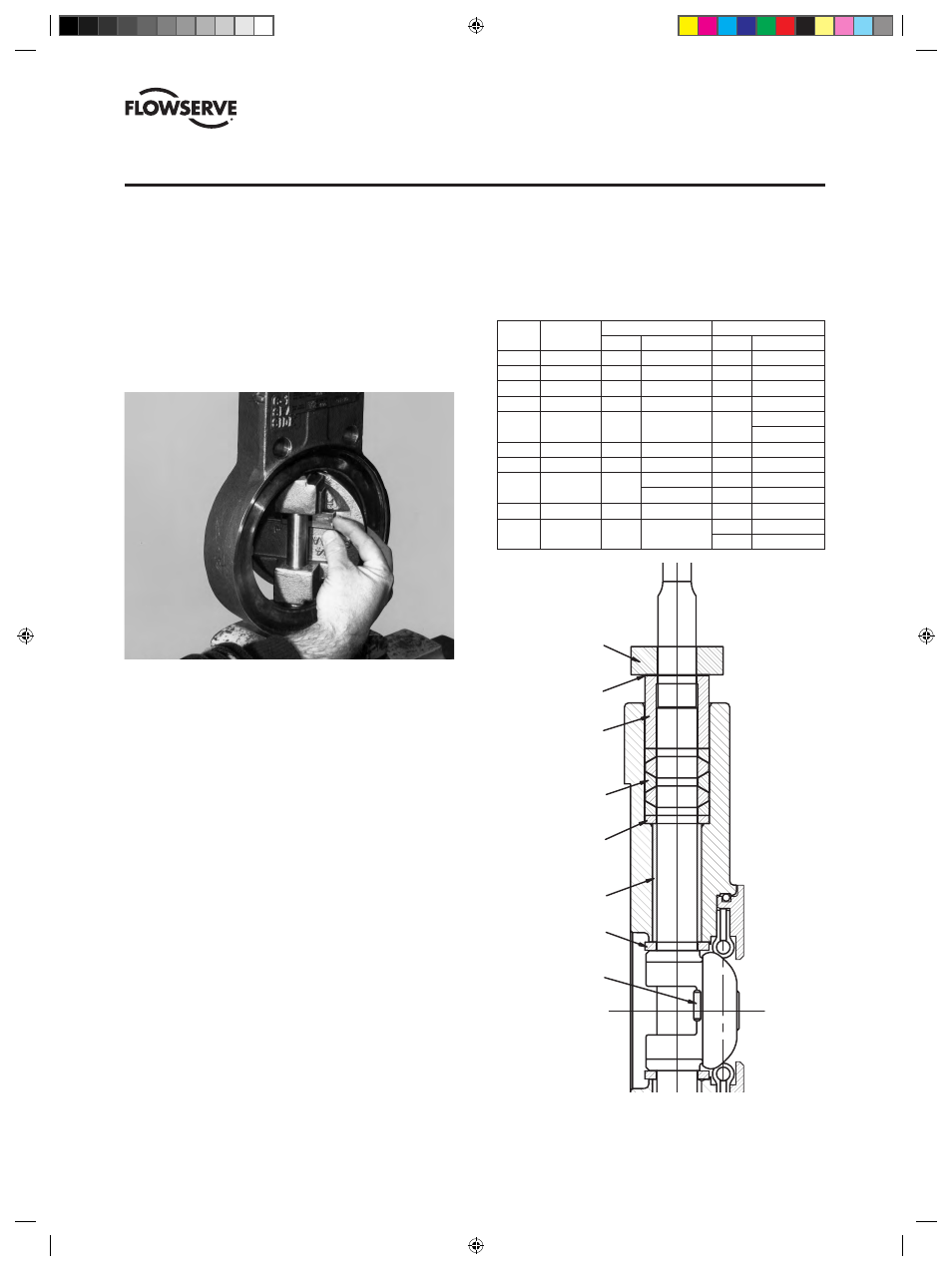
5. Insert the disc pin (thin end first) into the slot between
the disc shaft. When the pin is installed in the proper
orientation, the thick end of the pin will be adjacent to
the small drilled hole in the slot of the disc (adjacent
to the original pin weld). Also check alignment of
shaft double D to the disc face. The flat of the double
D should be parallel to the front face of the disc.
Improper orientation of disc pin will cause the shaft
flat and disc face to be off parallel by several degrees.
6. Using a punch and hammer on the thick end of the pin,
firmly set the pin. Check disc and shaft connection to
ensure there is no looseness.
7. Weld the thick end of the pin to the disc. Draw weld
into the small drilled hole in the pin slot of the disc to
act as a secondary mechanical lock. Be certain to use
weld rod compatible with pin and disc materials and
service environment.
8. Insert packing thrust washer, packing set and packing
gland into the packing bore of the valve body. Slide
the grounding spring over the shaft. Install packing
adjuster and adjuster nuts.
9. Tighten adjuster nuts to the torque specifications listed
on page 25 of this manual. Make certain to identify
the style of packing used in the valve in order to select
the proper fastener torque.
Note: Packing styles are
illustrated on page 25.
10. Install the seat package following the procedure for
seat replacement in Section IV.
11. If manual operators were removed, re-install
them using procedures in Section VIII for gears or
Section X for levers.
12. Operate the valves a few times to insure that the valve
disc turns freely into and out of the seat. Seat testing
of repaired valves is recommended.
Valve Pressure
Bottom Bearing
Top Bearing
Size
Class
Qty.
Length (in)
Qty. Length (in)
2 150/300 1 0.81 2 1.00
3 150/300 1
1.00
2
1.00
4 150/300 1
1.00
2
1.00
6 150/300 1
1.00
2
1.00
8 150 1 1.50
1 1.00
1.50
8
300
2
1.00
2
1.50
10
150
2
1.00
3
1.00
10 300 1 1.00 2 1.00
1.50
1
1.50
12
150
2
1.13
3
1.13
12 300 2
1.50 2 1.50
1
1.00
TABLE D – PTFE/Fiberglass Bearings
PACKING
ADJUSTER
PACKING
GLAND
GROUND
SPRING
STEM
PACKING
PACKING
THRUST
WASHER
STEM
BEARINGS
DISC
THRUST
BEARING
DISC
PIN
MEASURE
GAP
HERE
TO CENTER
DISC IN
BODY
GAP
SHOULD
BE
EQUAL
TOP
AND
BOTTOM
(DVENIM0390-02)-BX2001_update.indd 22
10/10/13 2:08 PM