Disassembly procedures for bonnet types – Flowserve V-377 R4 Edward Valves User Manual
Page 39
14. Lift out the cover assembly. During this
process, mark the spacer ring and
pressure-seal gasket at points (other
than the sealing surfaces) correspond-
ing to the previous marks on the body
and cover (see step 6). In laying the
parts aside for inspection, it is impera-
tive that they be placed carefully on a
bed of rags or other soft material to
avoid marring any machined surface,
particularly any seating and sealing
surfaces.
15. Inspection of the seat and hinge pins can
be made without further disassembly.
16. If removal of the disk is necessary,
proceed as follows:
NOTE: Pressure may be trapped in
the valve even though the system is
down, and care must be taken in
removing the hinge pin retainer. Once
the retainer bolts are completely
removed, the hinge pins are held
only by the friction of the pressure-
seal gasket against the hinge pin
bore. Trapped pressure could cause
the retainer and hinge pin to be
blown out with considerable force.
Therefore, care must be taken to
break the hinge pin and hinge pin
pressure-seal gasket loose before the
three retainer bolts are completely
removed.
a. Carefully loosen, but do not
remove, the hinge pin retainer
bolts.
b. Place a suitable spacer between
the hinge pin retainer and the
body. Insert a threaded stud (same
thread as the retainer bolts)
through the center hole of the
hinge pin retainer and thread into
the puller hole in the hinge pin.
c. Support the disk inside the body;
thread a nut onto the stud, and
tighten the nut until the pressure-
seal gasket and hinge pin is loose
and any pressure that may be
trapped in the valve is relieved. If
the hinge pin will not move, heat
the body boss (not more than
300° F) with an acetylene torch.
d. Remove the hinge pin retainer
bolts, hinge pin retainer, roll pin,
hinge pin, pressure-seal gasket
and torsion spring. During this
process, mark the position of the
hinge pin relative to the body with
prick punch marks. Tag each
hinge pin and torsion spring so
that each may be replaced on the
proper side of the valve. The tor-
sion springs are wound counter to
each other to provide a slight
restraint to valve opening and
assist in valve closing, making it
extremely important to reassemble
them correctly.
e. Remove the other hinge pin.
f. The disk can now be removed from
the body. Use caution not to dam-
age any machined or seating sur-
faces. In laying the parts aside for
inspection, it is imperative that they
be placed carefully on a bed of
rags or other soft material to avoid
damage.
17. The cover end opening should be
kept covered whenever possible.
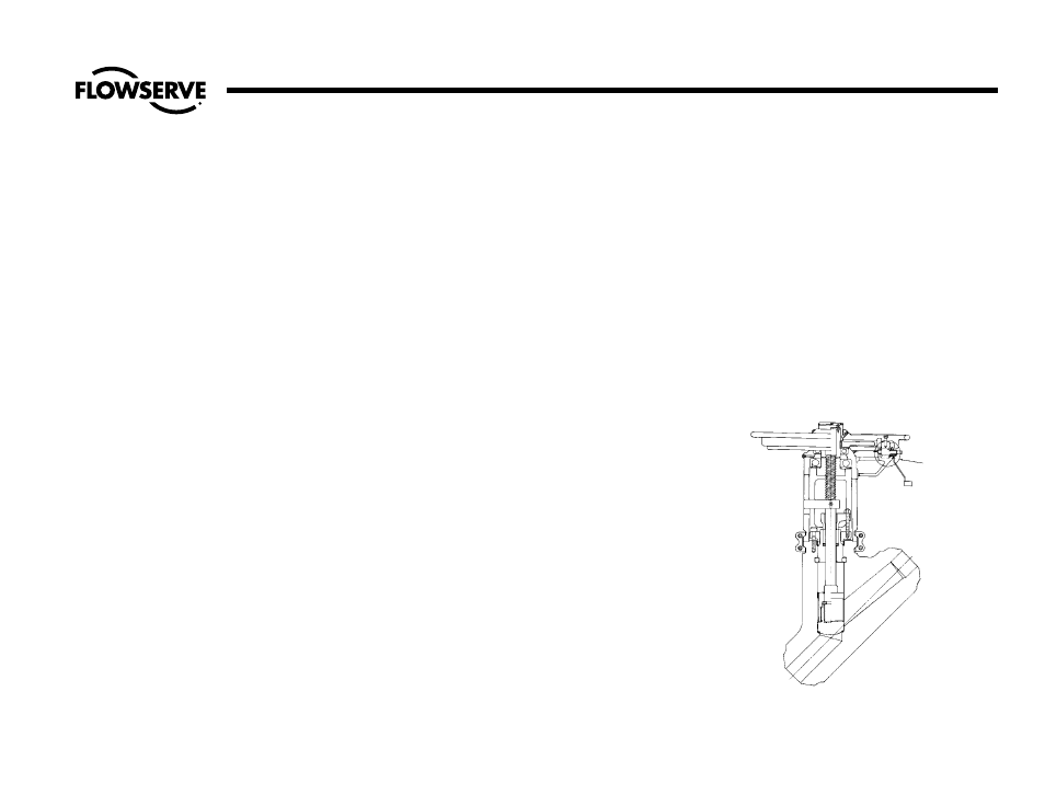
Type IV Pressure-Seal Bonnets –
Stop and Stop-Check (Non-Return)
Valves
See Illustration No. 27.
NOTE: All Type III Bonnets have non-
revolving stems.
1. Mark the body, yoke and yoke lock
ring with prick punch marks so that
the parts can be reassembled in their
original position.
2. Loosen the gland bolt nuts and tap
the gland, which should relieve any
pressure that might be trapped in the
valve. This is important.
SHOWN WITH
IMPACTOGEAR
Illustration No. 27
Type IV Bonnet on Stop-Check Valve
39
Flow Control Division
Edward Valves
Disassembly Procedures for Bonnet Types
(continued)