Flowserve V-377 R4 Edward Valves User Manual
Page 30
Non-Revolving Stem Valves with
Type II, III, or IV Bonnets
See valve Illustrations No. 23 (page 31),
No. 24 (page 34) and No. 27 (page 39).
See Handwheel Illustrations 10, 11, and
12 on pages 20 and 21. See Limitorque
Illustrations No. 16 (page 22) and 17
(page 23).
The following is applicable for Impactor
Handwheels and all types of Limitorque
operators, including the XT type.
1. Disconnect the electrical wiring to
Limitorque-operated valves.
2. Mark the body, yoke and yoke lock
ring with prick punch marks so that
the parts are referenced for
reassembly.
3. Make certain the packing gland nuts
are tight.
4. Position a chain hoist of suitable
capacity so the operator and yoke
assembly are supported in such a way
that the handwheel can still be rotated.
If the valve is installed with its stem
other than vertical, the hoist should be
positioned slightly away from the
handwheel in line with the stem.
5. Remove the yoke lock ring studs
and nuts.
6. Remove the yoke lock ring using a
small pry bar to separate the halves.
7. Loosen the stem guide collar nut,
back off the stem guide collar lock
screw and remove the stem guide col-
lar key. Lift the collar to the top of the
stem.
8. Turn the Impactor handwheel or
Limitorque handwheel in a direction
to close the valve, thus unscrewing
the operator yoke assembly from the
stem. Keep the weight on the hoist as
the handwheel is turned to prevent
damage to the stem threads. This is
important.
9. With the hoist, lift the whole assem-
bly clear of the stem simultaneously
slipping the stem guide collar off of
the stem.
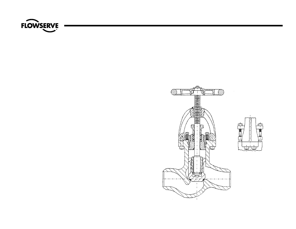
Illustration No. 22
Type II Bonnet on Revolving Stem Stop Valve
30
Flow Control Division
Edward Valves
Procedures for Removing Operator and Yoke Assembly as a Unit
(continued)