Flowserve V-377 R4 Edward Valves User Manual
Page 25
25
Flow Control Division
Edward Valves
7. Connect the electric current and
check this setting as follows:
a. Run the valve to mid-position by
hand.
b. Press the “open” pushbutton -
make sure moving the valve is in
the “open” direction.
c. Allow the limit switch to stop the
motor.
d. After the motor has stopped, turn
the valve by hand to make sure
their is sufficient clearance
between the valve backseat and
the position at which the valve
stem comes to rest.
8. To set the position for operation of
the indicating light, make sure the
torque switch is properly wired into
the closing circuit (see procedure for
setting torque switch below), and run
the valve to the closed position. Back
the valve off the seat to the desired
position and set the “closed” light
contact using the same procedure
outlined under steps 4, 5a, 5b, and
6, but use the intermittent gear shaft
for the light contacts.
9. When the settings are complete, the
setting rod should remain in the posi-
tion described in step 6.
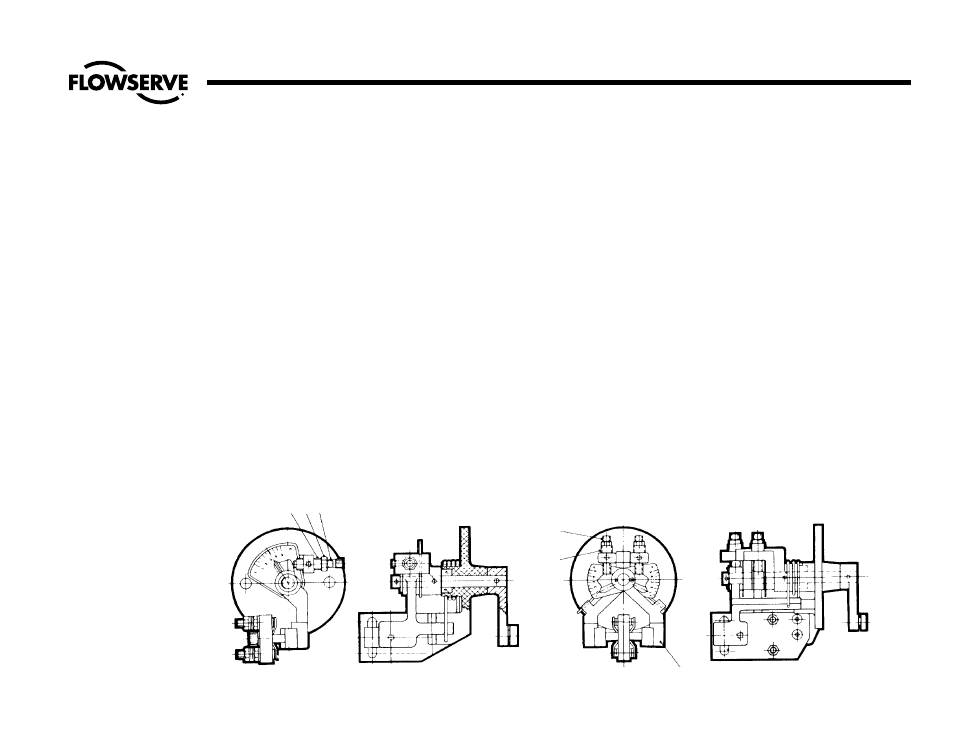
Torque Switch
See Illustration No. 19.
The procedure for setting the torque switch,
both single and double, is as follows:
Single Torque Switch
1. Make sure the electric current is off.
2. Loosen the jam nut (F).
3. Move the socket head adjusting
screw (G) in for light seating.
4. Close the valve by the motor and
test for tightness of closing. If the
valve closes tightly enough, tighten
the jam nut.
5. For heavier seating move the adjust-
ing screw (G) out and re-tighten the
jam nut.
6. The threaded bushing (E) is intended
to limit the maximum setting of this
torque switch and is locked in posi-
tion to limit the output torque to the
maximum safe rating for the unit.
Double Torque Switch
1. Make sure the electric current is off.
2. Loosen the jam nut (F). Note: The
right side of this switch (K) normally
limits the torque applied in closing
the valve. There are cases of special
valve assemblies where the right side
of this switch limits the torque in the
open direction. In all cases it is
recommended that this be checked
upon installation.
൴ ൵ ൶
൷
൹
Illustration No. 19
Single & Double Torque Switch Assemblies
ൺ
Procedures for Setting Actuator Torque and Limit Switches
(continued)