Flowserve ISC2PP User Manual
Page 9
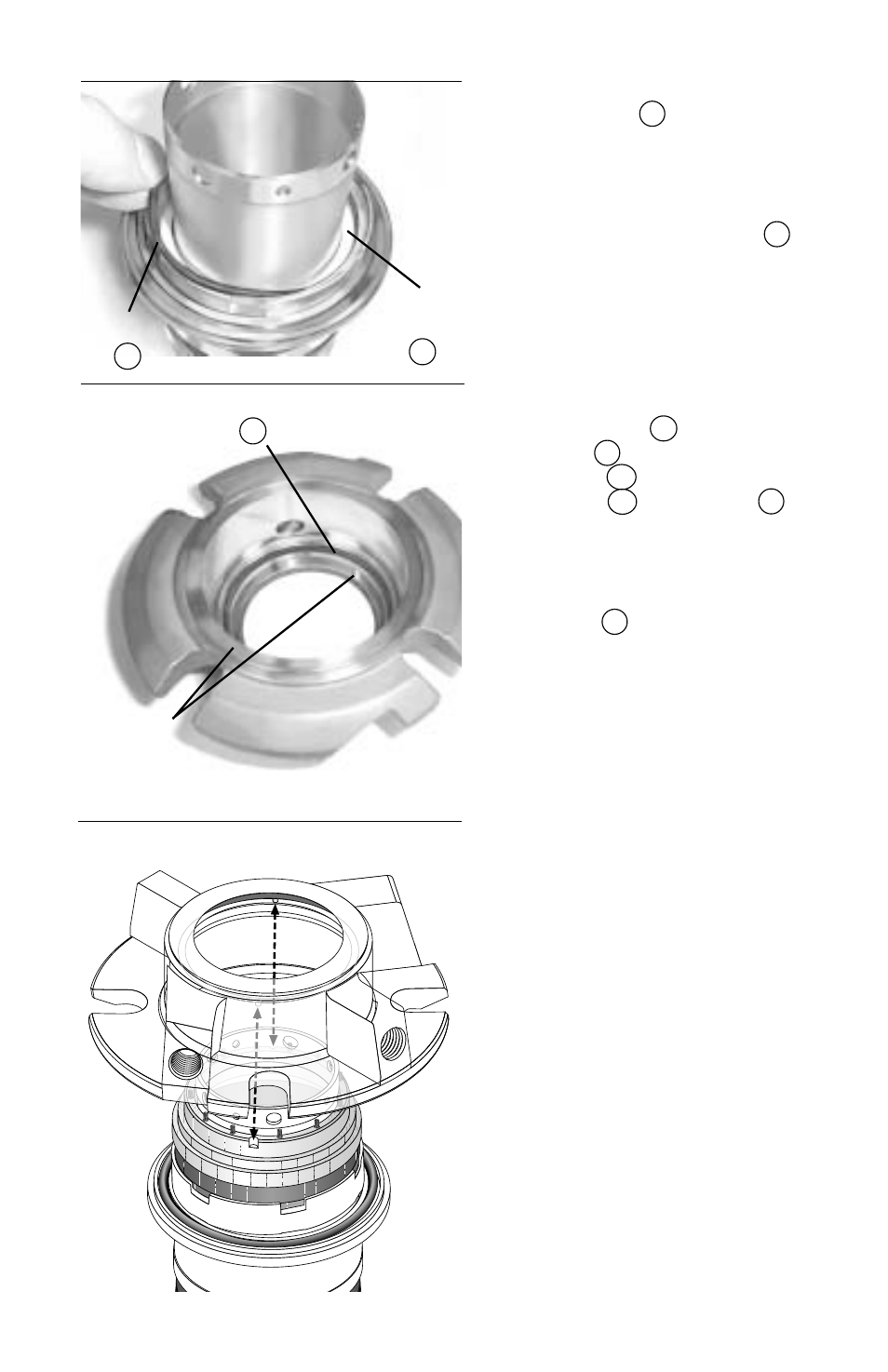
4.15 Insert the outboard vibration
dampener
M
into the rotor
carrier. Make sure that the
vibration dampener is fully
seated at the bottom of the
rotor carrier. Place the out-
board mating ring O-ring
6
in the O-ring groove of the
rotor carrier, which is behind
the surface with two drive
flats. (
Figure 18
)
4.16 Repeat steps 4.5 through 4.9
to assemble the outboard
mating ring
3B
, outboard
stator
3
, outboard stator
O-ring
P2
, outboard stator
carrier
SC
, and springs
C
onto the rotor carrier/sleeve
assembly.
4.17 Place the outboard dynamic
O-ring
P
in the dynamic
O-ring surface of the gland
assembly. (
Figure 19
)
4.18 Align the gland assembly drive
pins with the slots in the out-
side diameter of the stator
carrier and press the gland
onto the stator carrier, using
even hand pressure.
(
Figure 20
)
Caution: do not rotate the
gland to align pins while
pressing down. This could
damage the springs. Once
the gland is in the proper
position do not rotate it until
the seal is fully assembled to
ensure that the pins remain
engaged.
Figure 20
Figure 19
O-ring
P
Gland
Assembly
Drive Pins
Figure 18
9
O-ring
6
Vibration
Dampner
M