Flowserve Circulator User Manual
Page 7
7
Section C:
Kit Installation Instructions
Available kit options
Option 1:
Pressure switch
Part code UKDPU9802
Option 2:
Safety feature (accumulator)
Part code UKDPU9803
Option 3:
Level switch
Part code UKDPU9805
Option 4:
External heat exchanger
Part code UKDPU9806
Before installing any kit to the circulator, it must be shut
down and disconnected from the main power source. Safe-
ty glasses with side shields must be worn when working
on the unit. Clean the unit of all debris. Familiarize yourself
with these instructions and the components for each kit
before beginning any installation.
Option 1
The pressure switch kit includes:
• 1/4” NPT ball valve
• 1/4” x 1/2” NPT adapter
• Pressure switch, 1/2” NPT
Kit installation instructions
1. Apply Teflon tape and/or Jomar pipe dope or equal to
adapter threads. Start no closer to the end of the
threads than the 2nd thread.
2. Thread 1/4” side of adapter into ball valve finger tight.
Seal Support System
Part No.
Part No.
PSI
to
to
Xxxxxxx
Xxxxxxx Xxxxx Xxxx Xx
Xxxxx xx xxxxxxxxx
Xxxxx xx xxxxxxxxxxx
Xxxxxx
Xxxx Xx.
Xxxx xxxxxx xxxx
xxxxxxxx xx xxxx
xxxxxx xxxxxxxxx
xxxxxx xxxxxxxxx
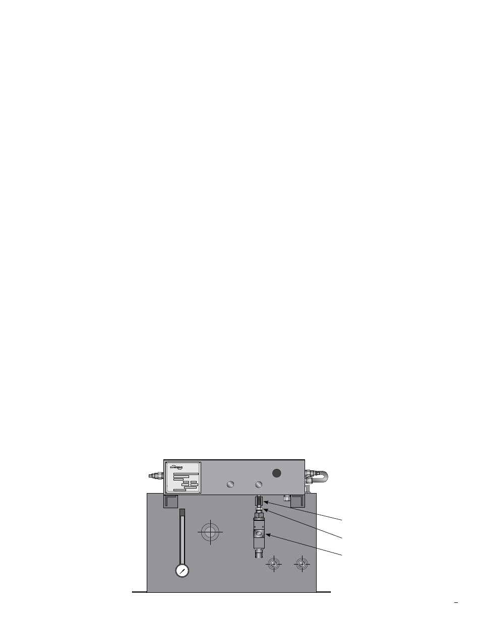
Figure 1
ball valve
adapter
pressure
switch
3. Thread 1/2” side of adapter into pressure switch finger
tight.
4. Place an open end wrench on the ball valve and an
open end wrench on the pressure switch connection
nut. Tighten connection until ball valve handle is facing
the pressure switch adjustment cover. Do not over
tighten.
5. Apply Teflon tape and/or Jomar pipe dope or equal
to the ball valve threads. Start no closer to the end of
the treads than the 2nd thread.
6. Clean any dirt or debris from the 1/4” NPT connection
on the bottom of the manifold block. Remove the 1/4”
NPT plug from the bottom of the manifold block.
7. Thread the pressure switch assembly into the mani-
fold block finger tight.
8. Place an open end wrench on the ball valve and
tighten into the manifold block. Tighten connections
until ball valve handle is facing away from the
circulator. Do not over tighten. See Figure 1.
9. Rotate the ball valve handle to the off position. Ball
valve is off when handle is rotated 90° to the ball valve
ports.
10. Installation is complete.
11. It is the responsibility of the customer to wire and set
the pressure switch.
12. The pressure switch can be put into service once the
unit is restarted and the customer has verified the
circulator is running normal. Rotate the ball valve
handle 90° to allow flow to the switch.