6 fastener torques, 7 renewal clearances, 8 disassembly – Flowserve FRBHJC User Manual
Page 30
FRBHJC USER INSTRUCTIONS ENGLISH 71569179 11-04
Page 30 of 42
®
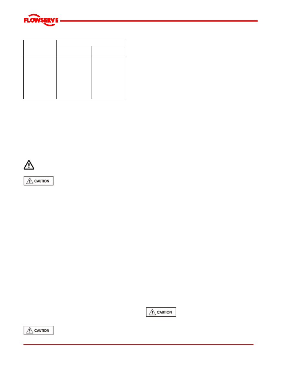
6.6 Fastener torques
Torque Nm (lb
Ÿft)
Bolt size
Pump feet
fasteners
All other
fasteners
M10 (3/8 in.)
M12 (1/2 in.)
M 16 (? in.)
M 20 (¾ in.)
M 24 (? in.)
M 27 (1 in.)
M 30 (1? in.)
M 36 (1? in.)
M 42 (1? in.)
23 (17)
54(40)
170 (125)
340 (250)
590 (435)
770 (570)
1 100 (810)
1 840 (1 350)
2 000 (1 475)
23 (17)
54 (40)
84 (62)
165 (120)
285 (210)
375 (275)
540 (400)
900 (660)
1 410 (1 040)
6.7 Renewal clearances
As wear takes place between the impeller and wear
ring the overall efficiency of the pump set will decrease.
To maintain optimum efficiency it is recommended that
rings are replaced and the impeller renovated when the
radial clearance detailed in section 3.4.2 has doubled
to 1.0 to 1.5 mm (0.040 to 0.060 in.), depending on
pump size.
6.8 Disassembly
Refer to section 1.6, Safety, before dismantling
the pump.
Before dismantling the pump for
overhaul, ensure genuine Flowserve replacement parts
are available.
Refer to sectional drawings for part numbers and
identification.
6.8.1 Pump unit
a) Isolate motor and lock off electrical supply in
accordance with local regulations.
b) Isolate discharge valves.
c) Remove coupling guards and disconnect the
coupling halves.
d) On units with larger drivers it is recommended to
remove the motor. If the bearing frame will be
dismantled it is suggested that the motor be left
connected to the motor. Unfasten the motorstand
from the top plate and remove.
e) Unscrew and remove discharge pipe flange bolts.
remove spool sections to allow pump to be
removed from well.
f) Unscrew and remove top plate mounting bolts.
g) Install eyebolts in top plate.
h) Using overhead crane or hoist, remove pump from
well.
i)
Place the pump assembly in a horizontal position,
preferably on a V-block fixture.
Adequate support must be provided to support columns
and liquid end to eliminate bending stresses imposed
on the shaft and column support pipes.
6.8.2
a) With casing [1] adequately supported by a hoist
unscrew and remove bolts holding casing [1].
Remove casing [1] away from support pipe [101].
b) Inspect wear plate [181] and casing [1], if
replacement of either component is required loosen
wear plate nuts and remove wear plate [181].
c) Remove impeller nut [24], application of heat may
be required to break bond of resinous sealant on
threads [heat evenly).
d) Remove impeller [2]. For ease of removal, the
impeller hub is slotted to accept a standard bearing
puller.
e) Remove impeller key [32] and sleeve stop [82].
6.8.3 Stuffing Box Head
a) Remove stuffing box head [33A] from the support
pipe [101].
b) Inspect lower bushing [39], if replacement is
required carefully press bearing out.
c) Remove the support pipe [101].
d) Inspect shaft sleeve [6] for excessive wear.
Remove shaft sleeve only if replacement is
necessary. The sleeve is a hook type that is
normally held in place with an anaerobic sealant.
6.8.4
Bearing Frame
a) If the motor stool was not removed with the motor it
should be unfastened from the bearing frame now.
b) Unfasten and remove the line bearing cover from
the bearing frame.
c) Loosen and remove jacking stud nuts and bolts
from the thrust bearing housing [33]
d) Remove the shaft assembly from the bearing frame
[19], set on wooden V-blocks.
6.8.5
Thrust bearings
a) Loosen cap screws from thrust bearing cover [37];
remove cover.
b) Slide thrust bearing housing [33] towards the
inboard line bearing to expose bearings.
c) To remove the bearings first bend the locking tab of
the bearing lock washer [22A] from lock nut [22].
d) Using a hook type wrench unscrew the lock nut
from the shaft.
e) The bearings may be removed from the shaft by
using a puller or cutting torch.
If a torch is used caution is required to prevent
damage to the shaft.