Flowserve NM User Manual
Page 19
NM USER INSTRUCTIONS ENGLISH 71576289 - 11/09
Page 19 of 48
The oil filled bottle should then be refitted so as to
return it to the upright position. Filling should be
repeated until oil remains visible within the bottle.
Approximate oil volumes are shown in section
6.2.1.2, Oil lubricated bearings.
Grease lubricated pumps and electric motors are
supplied pre-greased.
Other drivers and gearboxes, if appropriate, should
be lubricated in accordance with their manuals.
In the case of product lubricated
bearings the source of product supply should be
checked against the order. There may be
requirements for an external clean supply, particular
supply pressure or the commencement of lubrication
supply before pump start-up.
5.2 Direction of rotation
Starting or operating pumps with the
wrong direction of rotation can be harmful to the
pumps. Ensure that the pump rotation is the same
as the arrow on the pump casing.
It is preferable to check the direction of rotation
before installing the coupling. If not, the pump must
be filled in with the liquid before start-up.
If maintenance work has been
carried out to the site's electricity supply, the
direction of rotation should be re-checked as
above in case the
5.3 Guarding
Guarding is supplied fitted to the pump set.
If this has been removed or disturbed ensure
that all the protective guards around the pump
coupling and exposed parts of the shaft are securely
fixed.
5.4 Priming and auxiliary supplies
Where there is any risk of the pump being run
against a closed valve generating high liquid and
casing external surface temperatures it is
recommended that users fit an external surface
temperature protection device.
Ensure all electrical, hydraulic,
pneumatic, sealant and lubrication systems (as
applicable) are connected and operational.
Ensure the inlet pipe and pump
casing are completely full of liquid before starting
continuous duty operation.
These operations must be carried out by personnel
with approved qualifications.
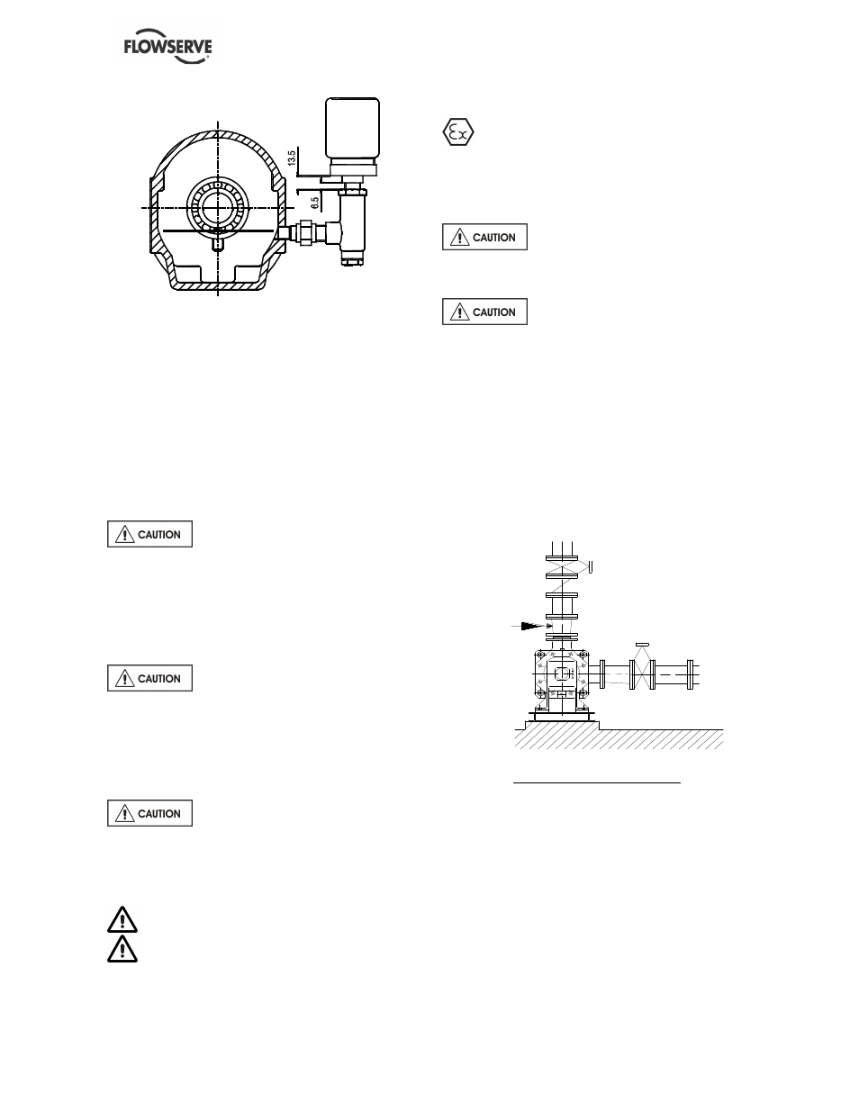
5.4.1 Priming of a flooded pump
As discharge valve is closed, fill the pump by
opening the valve at suction. Let air escape by
removing the plugs situated on the flange of the
discharge casing and suction casing (for the 102-
122-152-202-252-352 NM pumps). For the 32 to 201
NM pumps, plugs are located on pipework.
Air escape
Priming of a flooded pump
5.4.2 Priming of a sump suction pump
* With foot valve:
a) Fill suction pipe and casing with liquid from an
independent source (pressure 1 to 2 bars).
b) Let air escape by removing the plugs situated on
the flange of the discharge casing and suction
casing (for the 102-122-152-202-252-352 NM
pumps). For the 32 to 201 NM pumps, plugs are
located on pipework.
c) When the pump is totally free of air bubbles,
replace the plugs.