4 performance and operating limits, 4 installation, 1 location – Flowserve CPXPM User Manual
Page 11: 2 part assemblies, 3 foundation
CPXPM USER INSTRUCTIONS ENGLISH 71569160 09-09
Page 11 of 28
flowserve.com
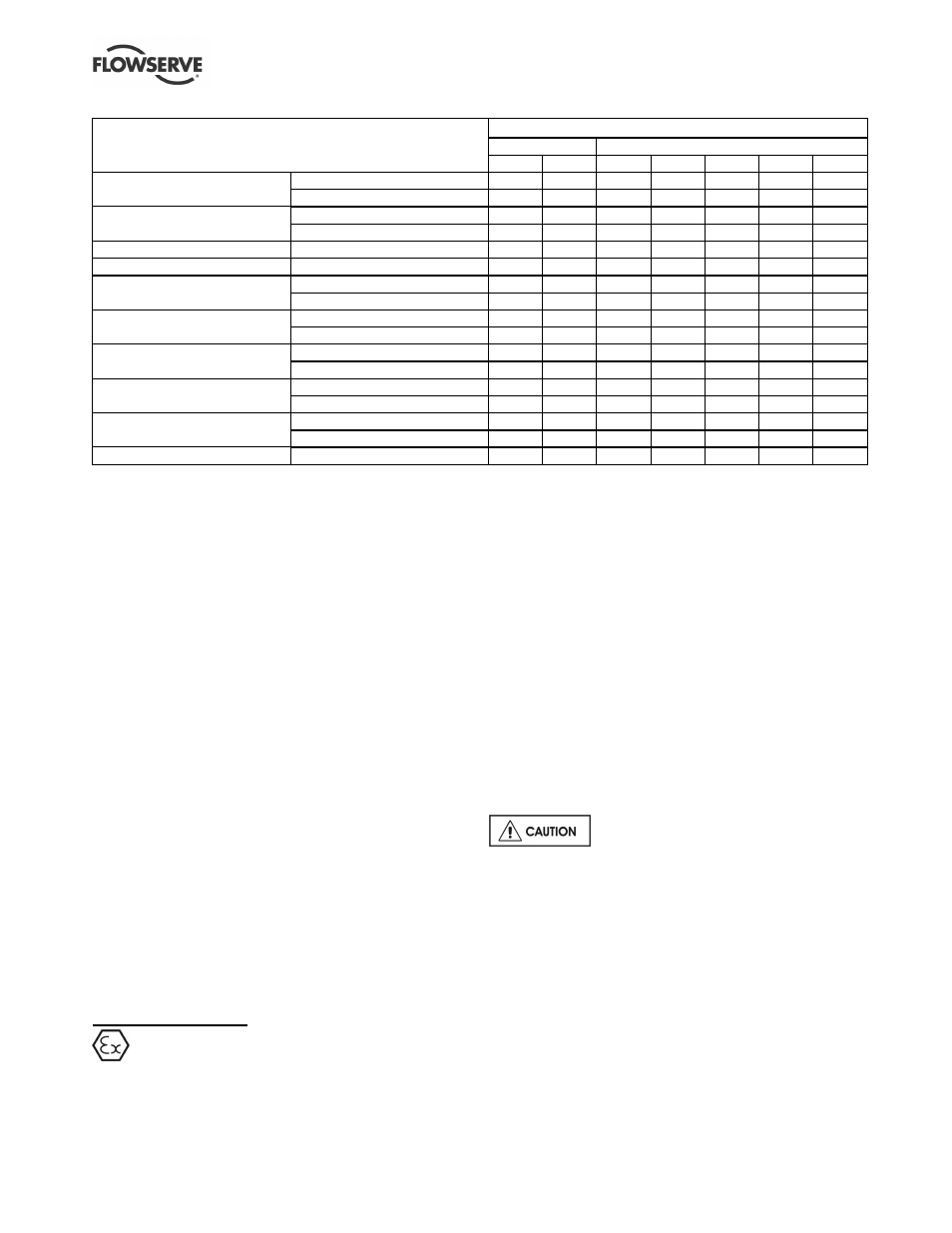
Motor frame size
Flange mounted
Foot/flange mounted
Motor manufacturer and type
80
90
100/112
132
160
180
200
TECO standard
Standard motor acceptable?
Yes
No
No
Yes
Yes
Yes
Yes
'AEBB'
With alternative 2A grease?
N/A
Yes (1) Yes (1)
N/A
N/A
N/A
N/A
TECO
Standard motor acceptable?
No
No
No
No
No
-
-
aluminium range
With drive end bearing location?
Yes
Yes
Yes
Yes
Yes
-
-
ABB standard 'M2AA'
Standard motor acceptable?
Yes
Yes
Yes
Yes
Yes
Yes
Yes
LEROY SOMER standard 'LSB 5'
Standard motor acceptable?
Yes
Yes
Yes
Yes
Yes
Yes
Yes
ELECTRODRIVES
Standard motor acceptable?
No
No
No
No
Yes
Yes
Yes
standard 'ALPAK'
With drive end bearing location?
Yes (2)
Yes (2) Yes (2)
Yes (2)
N/A
N/A
N/A
BROOK HANSEN
Standard motor acceptable?
No
No
No
No
No
No
No
standard 'ARGUS'
With drive end bearing location?
Yes
Yes
Yes
Yes
Yes
Yes
Yes
SIEMENS
Standard motor acceptable?
No
No
No
No
Yes
Yes
Yes
standard 'LA'
With drive end bearing location?
Yes
Yes
Yes
Yes
N/A
N/A
N/A
VEM
Standard motor acceptable?
No
No
No
No
No
No
No
Standard 'K21R'
With drive end bearing location?
Yes
Yes
Yes
Yes
Yes
Yes
Yes
GAMAK
Standard motor acceptable?
No
No
No
No
No
No
No
Standard 'AGM'/'AG'
With drive end bearing location?
Yes
Yes
Yes
Yes
Yes
Yes
Yes
WEG 'W21' cast iron
Standard motor acceptable?
Yes
Yes
Yes
Yes
Yes
Yes
Yes
Notes: N/A = Not applicable.
1) The standard grease used on TECO motor frames 90, 100 and 112 is unsuitable as it does not generate sufficient lubricating film
thickness with the relatively low viscosity 5K grease. The alternative grease 2A is acceptable and must be specified.
2) Standard ALPAK motor frames 80 to 132 inclusive have bearings at the non-drive end with a special retention device. This device is not
acceptable for use with the CPXPM unit. The ALPAK machine with bearing cap locating the drive end bearing is acceptable.
3.4 Performance and operating limits
This product has been selected to meet the
specifications of the purchase order. See section 1.5.
The following data is included as additional
information to help with your installation. It is typical,
and factors such as temperature, materials, and seal
type may influence this data. If required, a definitive
statement for your particular application can be
obtained from Flowserve.
3.4.1 Operating limits
3.4.1.1 Temperature limits of working fluids
Horizontal units: -20 ºC (-4 ºF) to +160
ºC (320 ºF).
(These limits subject to approved mechanical seal
area design.)
3.4.1.2 Ambient temperature
These units are normally fitted with TEFC motors
suitable for an ambient temperature up to 40 ºC
(104 ºF). Specific pumps may be fitted with motors to
suit client's requirements with other ambient
temperature limits - see motor nameplate for details.
4 INSTALLATION
Equipment operated in hazardous locations
must comply with the relevant explosion protection
regulations. See section 1.6.4, Products used in
potentially explosive atmospheres.
4.1 Location
The pump should be located to allow room for access,
ventilation, maintenance and inspection with ample
headroom for lifting and should be as close as
practicable to the supply of liquid to be pumped. Refer
to the general arrangement drawing for the pump set.
4.2 Part assemblies
These pumps are not normally supplied in part
assemblies but special accessories such as loose
orifice plates are supplied loose. Ensure these are
incorporated in the final installation.
4.3 Foundation
There are many methods of installing
pump units to their foundations. The correct method
depends on the size of the pump unit, its location and
noise and vibration limitations. Non-compliance with
the provision of correct foundation and installation
may lead to failure of the pump and, as such, would
be outside the terms of the warranty.
Where a baseplate is used, it should be mounted onto
a firm foundation, either an appropriate thickness of
quality concrete or sturdy steel framework. It should
be packed or shimmed underneath to avoid distortion
when pulled down onto the surface of the foundation.
Where supplied, install the baseplate onto packing
pieces evenly spaced and adjacent to foundation bolts.