3 impeller clearance, 4 direction of rotation, 5 guarding – Flowserve BP User Manual
Page 21: 6 priming and auxiliary supplies
BP USER INSTRUCTIONS ENGLISH 85392725 10-09 (E)
Page 21 of 44
flowserve.com
5.2.2
Lubrication schedule
Oil should be changed after the first 400 hours use.
Normal oil change intervals are 4 000 operating hours
or at least every 6 months. For pumps on hot service
or in severely damp or corrosive atmosphere, the oil
will require changing more frequently. Lubricant and
bearing temperature analysis can be useful in
optimizing lubricant change intervals.
Lubricant quantities will be found in the technical data
supplied with your pump.
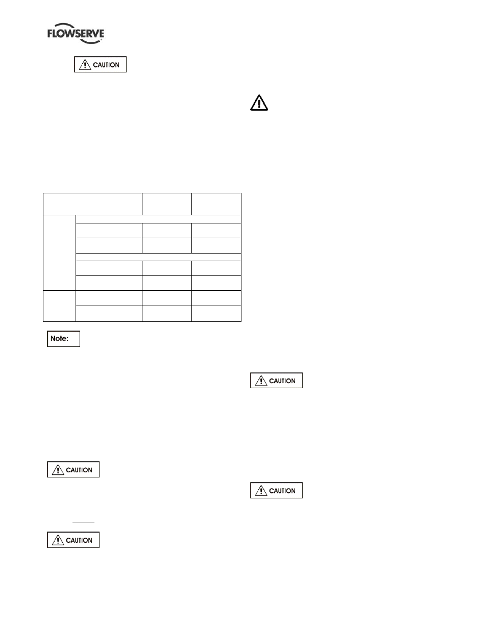
5.2.3 Oil
temperature
Oil temperature of the journal and thrust bearings
should be maintained as listed below.
Place of Measurement
Normal
Temperature
Maximum
Allowable
Temperature
Radial Side
at the Bearing
Retainer
49-82°C (120-
180°F)
93℃ (200°F)
at the Oil Exhaust
44-71°C (110-
160°F)
85℃ (185°F)
Thrust Side
at the Bearing
Retainer
49-82°C (120-
180°F)
93℃ (200°F)
Journal
Bearing
at the Oil Exhaust
44-71°C (110-
160°F)
85℃ (185°F)
at the Thrust Shoe
49-82°C (120-
180°F)
93℃ (200°F)
Thrust
Bearing
at the Oil Exhaust
44-71°C (110-
160°F)
85℃ (185°F)
The minimum bearing oil supply
temperature is 15°C (59°F). If necessary, the oil in
the reservoir should be heated by the immersion
heater normally provided.
5.3 Impeller
clearance
The impeller clearance is set in the factory. This may
require adjustment because of piping attachment or
increase in temperatures. For impeller clearance
refer to API 610/ISO 13709 minimum running
clearances.
5.4 Direction
of
rotation
Serious damage can result if the pump
is started or run in the wrong direction of rotation.
The pump is shipped with the coupling element
removed. Ensure the direction of rotation of the motor is
correct before fitting the coupling element. Direction of
rotation must correspond to the direction arrow.
If maintenance work has been carried
out to the site's electricity supply, the direction of
rotation should be re-checked as above in case the
supply phasing has been altered.
5.5 Guarding
Guarding is supplied fitted to the pump set.
Fasteners for guards must remain captive in the
guard to comply with the Machinery Directive
2006/42/EC. When releasing guards, the fasteners
must be unscrewed in an appropriate way to ensure
that the fasteners remain captive.
Whenever guarding is removed or disturbed ensure
that all the protective guards are securely refitted
prior to start-up. If they have been removed or
disturbed ensure that all the protective guards are
securely refitted.
5.6 Priming and auxiliary supplies
5.6.1 Filling and priming:
a) Do not run the pump dry.
b) Fill the pump with liquid before starting.
c) Open the vent valve installed at the pump or the
discharge piping midway in order to evacuate air
and gases from the pump.
d) Confirm that the pump is filled with liquid.
e) If the suction pressure is lower than atmosphere,
carry out the priming of pump by using a priming
device such as vacuum pump or ejector. While
evacuating air and gas from the pump, perform
by repeating to turn the pump shaft by hand.
5.6.2 Warming:
Perform warming prior to operating the
pump with liquid over 100°C (212°F)
Use warming piping if installed.
It is recommended to perform warming at the rate of
2~3°C (4~6°F) /min temperature rise. Start-up the
pump after differential temperature between the top
and bottom of the pump barrel is less than 35°C
(63°F), and the lower of the two temperatures is
within 30°C (54°F) of the stream temperature to
which the pump will be exposed when operating, as a
standard.
Do not fill the pump rapidly with high
temperature liquid.
In the case that the temperature difference between
pump casing and liquid, or the temperature difference
between the top and bottom of the pump barrel
cannot be measured accurately, it is possible to start-
up the pump if the shaft rotates smoothly by turning it
by hand, when the casing temperature will have
reached a saturated temperature.