Figure 6.19, Figure 6.20 – Flowserve Mark 3 Sealed Metallic Durco User Manual
Page 52
MARK 3 USER INSTRUCTIONS ENGLISH 71569102 01-13
Page 52 of 72
flowserve.com
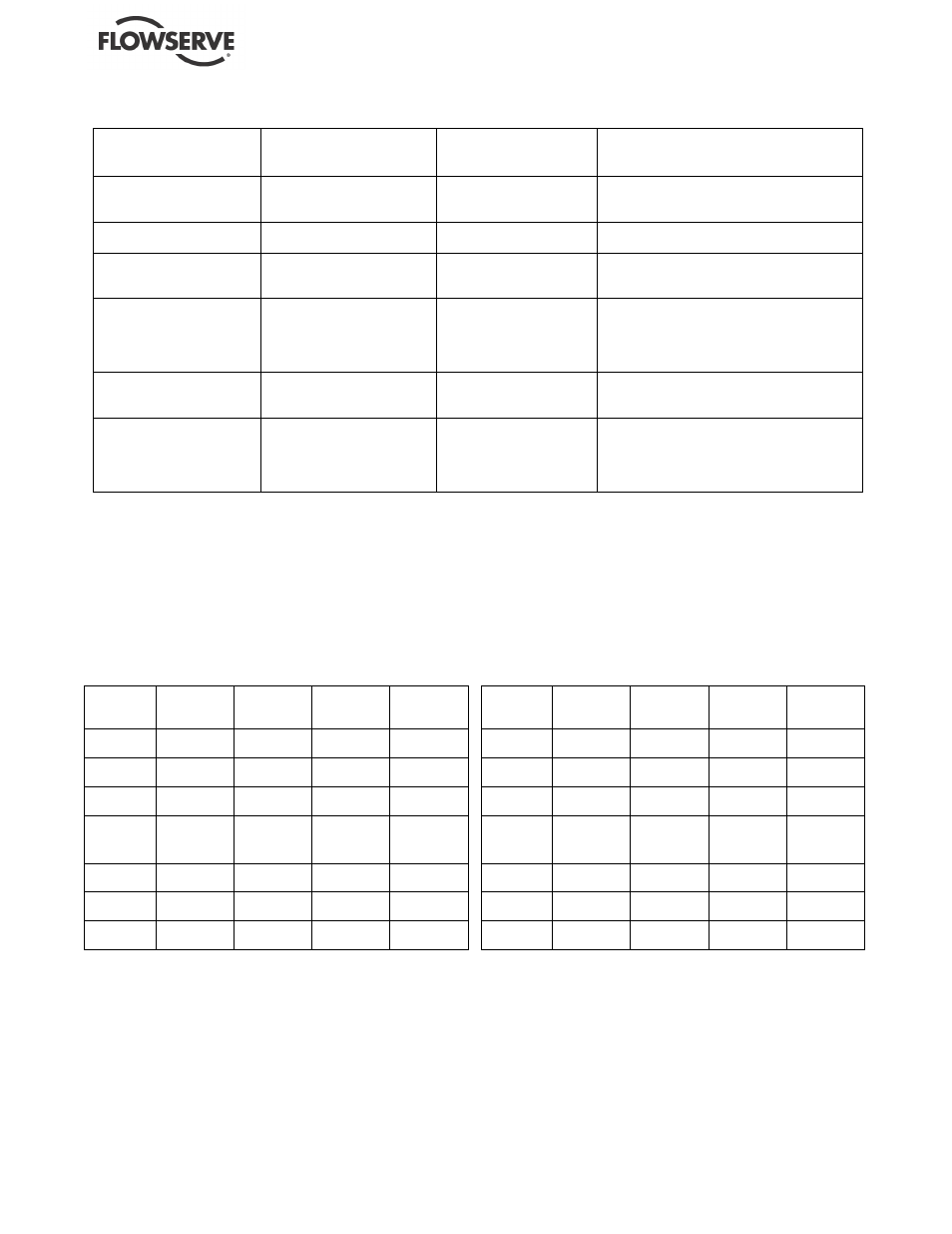
Figure 6.18
Topic
ASME B73.1M standard
mm (in.)
Suggested by major
seal vendors
mm (in.)
Suggested and/or provided by Flowserve
mm (in.)
Shaft
Diameter tolerance,
under bearings
n/s
0.005 (0.0002)
Impeller
Balance
See note 1
Bearing housing
Diameter (ID) tolerance
at bearings
n/s
0.013 (0.0005)
Power end assembly
Shaft runout
Shaft sleeve runout
Radial deflection - static
Shaft endplay
0.05 (0.002)
0.05 (0.002)
n/s
n/s
0.03 (0.001)
0.05 (0.002)
0.076 (0.003)
0.05 (0.002)
0.05 (0.002)
0.05 (0.002)
0.05 (0.002)
Seal chamber
Face squareness to shaft
Register concentricity
0.08 (0.003)
0.03 (0.001)
0.13 (0.005)
0.08 (0.003)
0.13 (0.005)
Complete pump
Shaft movement caused by
pipe strain
Alignment
Vibration at bearing housing
n/s
n/s
See note 3
0.05 (0.002)
0.05 (0.002)
See note 2
See note 3
n/s = not specified.
1. The maximum values of acceptable unbalance are:
1500 r/min: 40 g
·
mm/kg (1800 r/min: 0.021 oz-in/lb) of mass.
2900 rpm: 20 g
·
mm/kg (3600 rpm: 0.011 oz-in/lb) of mass.
Flowserve performs a single plane spin balance on most impellers. The following impellers are exceptions: 10X8-14, 10X8-16 and
10X8-16H. On these Flowserve performs a two plane dynamic balance, as required by the ASME B73.1M standard. All balancing,
whether single or two plane, is performed to the ISO 1940 Grade 6.3 tolerance criteria.
2. The ASME B73.1M standard does not specify a recommended level of alignment. Flowserve recommends that the pump and motor shafts
be aligned to within 0.05 mm (0.002 in.) parallel FIM (full indicator movement) and 0.0005 mm/mm (0.0005 in./in.) angular FIM. Closer
alignment will extend MTBPM. For a detailed discussion of this subject see the
Alignment section of this manual.
3. The ASME B73.1M, paragraph 5.1.4.
Figure 6.19
OB
Brg/Shaft
mm (in.)
Group 1
Group 2
Group 3
Group 3HD
Bearing
30.000/29.990
(1.1811/1.1807)
50.000/49.987
(1.9685/1.9680)
70.000/69.985
(2.7559/2.7553)
75.000/74.985
(2.9528/2.9522)
Shaft
30.013/30.003
(1.1816/1.1812)
50.013/50.003
(1.9690/1.9686)
70.015/70.002
(2.7565/2.7560)
75.016/75.004
(2.9534/2.9529)
Fit
0.023T/0.003T
(0.0009T/0.0001T)
0.026T/0.003T
(0.0010T/0.0001T)
0.030T/0.002T
(0.0012T/0.0001T)
0.031T/.004T
(.0012T/.0001T)
IB
Brg/Shaft
mm (in.)
Group 1
Group 2
Group 3
Group 3HD
Bearing
35.000/34.989
(1.3780/1.3775)
50.000/49.987
(1.9685/1.9680)
70.000/69.985
(2.7559/2.7553)
85.000/84.975
(3.3465/3.3455)
Shaft
35.014/35.004
(1.3785/1.3781)
50.013/50.003
(1.9690/1.9686)
70.015/70.002
(2.7565/2.7560)
85.019/85.004
(3.3472/3.3466)
Fit
0.025T/0.004T
(0.0010T/0.0001T)
0.026T/0.003T
(0.0010T/0.0001T)
0.030T/0.002T
(0.0012T/0.0001T)
.044T/.004T
(.0017T/.0001T)
Figure 6.20
OB
Brg/Carrier
mm (in.)
Group 1
Group 2
Group 3
Group 3HD
Bearing
71.999/71.986
(2.8346/2.8341)
110.000/109.985
(4.3307/4.3301)
150.000/149.979
(5.9055/5.9047)
160.000/159.975
(6.2992/6.2982)
Carrier
71.999/72.017
(2.8346/2.8353)
110.007/110.022
(4.3310/4.3316)
150.002/150.030
(5.9056/5.9067)
160.043/160.002
(6.3009/6.2993)
Fit
0.031L/0.000L
(0.0012L/0.0000L)
0.037L/0.007L
(0.0015/0.0003L)
0.051L/0.002L
(0.0020L/0.0001L)
.068L/.002L
(.0027L/.0001L)
IB Brg /
Housing
mm (in.)
Group 1
Group 2
Group 3
Group 3HD
Bearing
71.999/71.986
(2.8346/2.8341)
110.000/109.985
(4.3307/4.3301)
150.000/149.979
(5.9055/5.9047)
150.000/149.975
(5.9055/5.9045)
Housing
71.999/72.017
(2.8346/2.8353)
110.007/110.022
(4.3310/4.3316)
150.007/150.025
(5.9058/5.9065)
150.025/150.007
(5.9065/5.9058)
Fit
0.031L/0.000L
(0.0012L/0.0000L)
0.037L/0.007L
(0.0015L/0.0003L)
0.046L/0.007L
(0.0018L/0.0003L)
.050L/.007L
(.0020L/.0003L)