4 performance and operating limits, 4 installation, 1 location – Flowserve WMV IDP User Manual
Page 11: 2 part assemblies, 3 foundation, Foundation (4.3), Location (4.1), Part assemblies (4.2), Performance (3.4)
WMV, WMVS USER INSTRUCTIONS ENGLISH 26999970 10-12
Page 11 of 28
flowserve.com
3.3.5 Seal housing
The seal housing has spigots between the pump
casing and bearing housing for optimum
concentricity.
3.3.6 Shaft seal
The mechanical seal(s) attached to the pump shaft
seals the pumped liquid from the environment.
3.3.7 Driver
The pump is driven by a close coupled electric motor.
The position of the terminal box can be changed by
rotating the complete motor. To do this, remove the
fasteners from the motor flange, rotate the motor and
refit the fasteners.
3.3.8 Accessories
Accessories may be fitted when specified by the
customer.
3.4 Performance and operating limits
This product has been selected to meet the
specifications of the purchase order. (See section 1.5.)
These pumps are generally fitted with TEFC motors
with an ambient temperature limit of 40 °C. Specific
pumps may be fitted with motors to suit client's
requirements with other ambient temperature limits -
see motor nameplate for details.
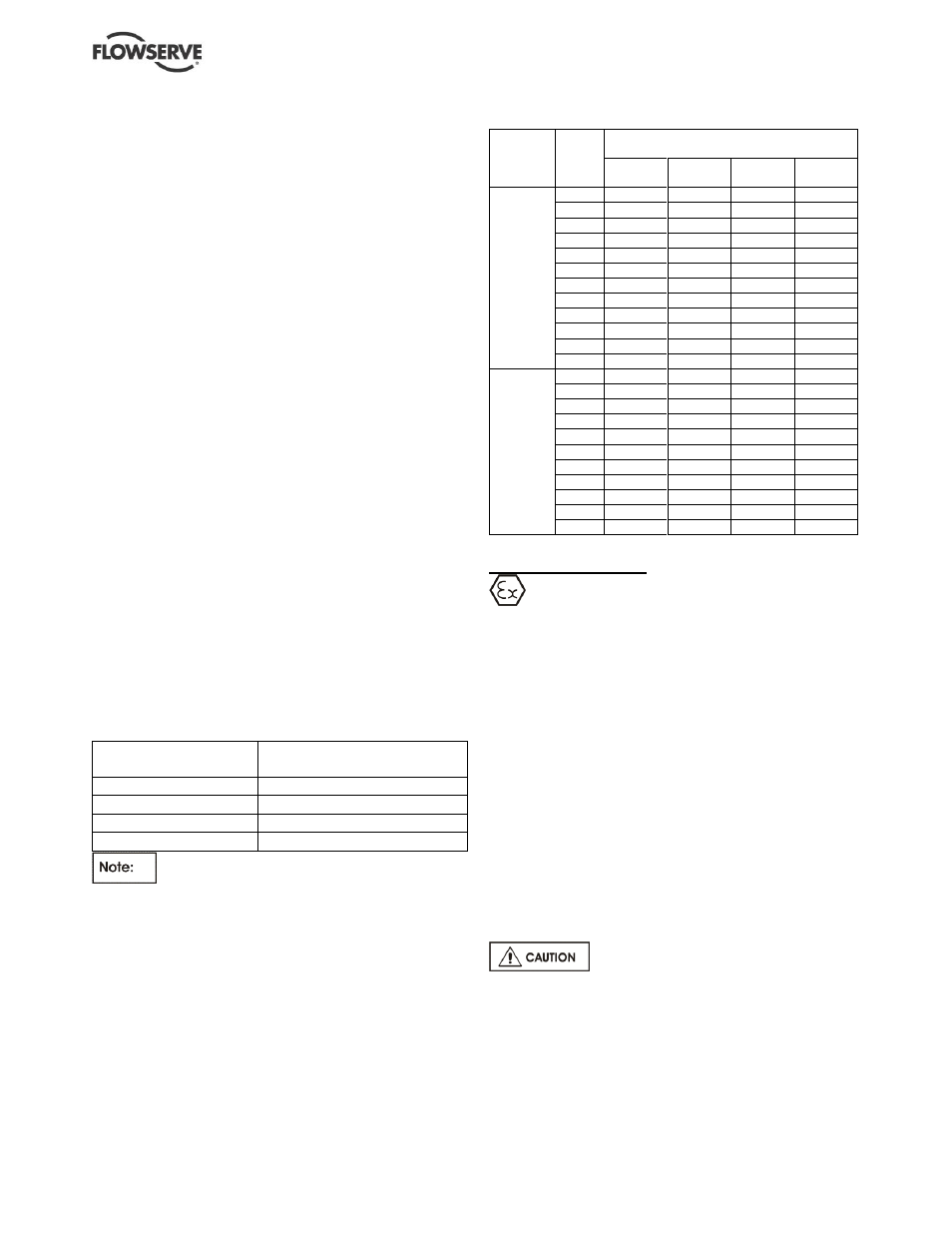
3.4.1 Pressure limits
The operating pressure has been selected to meet
your specified requirements. See paragraph 1.5,
Duty conditions, for details.
Pump size
Max. working pressure
bar g (psi)
5WMV, 8WMV
24 (348)
16WMV
30 (435)
5WMVS, 8WMVS
29.5 (428)
16WMVS
41 (595)
Maximum suction pressure is dependent on
the number of pump stages. Suction pressure plus
closed valve head must not exceed the maximum
working pressure stated above.
3.4.2 Temperature limits
Pump
size
No of
stages
Maximum liquid temperature ºC (ºF)
at pump rotational speed
3 500
rpm
2 900
rpm
1 750
rpm
1 450
rpm
5 and 8
WMV(S)
30
N/A
35 (95)
35 (95)
35 (95)
24
N/A
100 (212) 100 (212) 100 (212)
20
35 (95)
100 (212) 100 (212) 100 (212)
18
35 (95)
100 (212) 100 (212) 100 (212)
16
100 (212) 100 (212) 100 (212) 100 (212)
14
100 (212) 100 (212) 100 (212) 100 (212)
12
100 (212) 100 (212) 100 (212) 100 (212)
10
100 (212) 100 (212) 100 (212) 100 (212)
8
100 (212) 100 (212) 100 (212) 100 (212)
6
100 (212) 100 (212) 100 (212) 100 (212)
5
100 (212) 100 (212) 100 (212) 100 (212)
4
100 (212) 100 (212) 100 (212) 100 (212)
16
WMV(S)
and
WMV(S)
24
N/A
35 (95)
35 (95)
35 (95)
20
N/A
35 (95)
35 (95)
35 (95)
18
N/A
35 (95)
35 (95)
35 (95)
16
N/A
100 (212) 100 (212) 100 (212)
14
35 (95)
100 (212) 100 (212) 100 (212)
12
35 (95)
100 (212) 100 (212) 100 (212)
10
100 (212) 100 (212) 100 (212) 100 (212)
8
100 (212) 100 (212) 100 (212) 100 (212)
6
100 (212) 100 (212) 100 (212) 100 (212)
5
100 (212) 100 (212) 100 (212) 100 (212)
4
100 (212) 100 (212) 100 (212) 100 (212)
4 INSTALLATION
Equipment operated in hazardous locations
must comply with the relevant explosion protection
regulations. See section 1.6.4, Products used in
potentially explosive atmospheres.
4.1 Location
The pump should be located to allow room for access,
ventilation, maintenance and inspection with ample
headroom for lifting and should be as close as
practicable to the supply of liquid to be pumped. Refer
to the general arrangement drawing for the pump set.
4.2 Part assemblies
These pumps are not normally supplied in part
assemblies but special accessories such as loose
orifice plates are supplied loose. Ensure these are
incorporated in the final installation.
4.3 Foundation
There are many methods of installing
pump units to their foundations. The correct method
depends on the size of the pump unit, its location and
noise and vibration limitations. Non-compliance with
the provision of correct foundation and installation
may lead to failure of the pump and, as such, would
be outside the terms of the warranty.