7 disassembly – Flowserve HED Worthington User Manual
Page 37
HED/HED-DS USER INSTRUCTIONS ENGLISH 85392695 – 06/14
Page 37 of 64
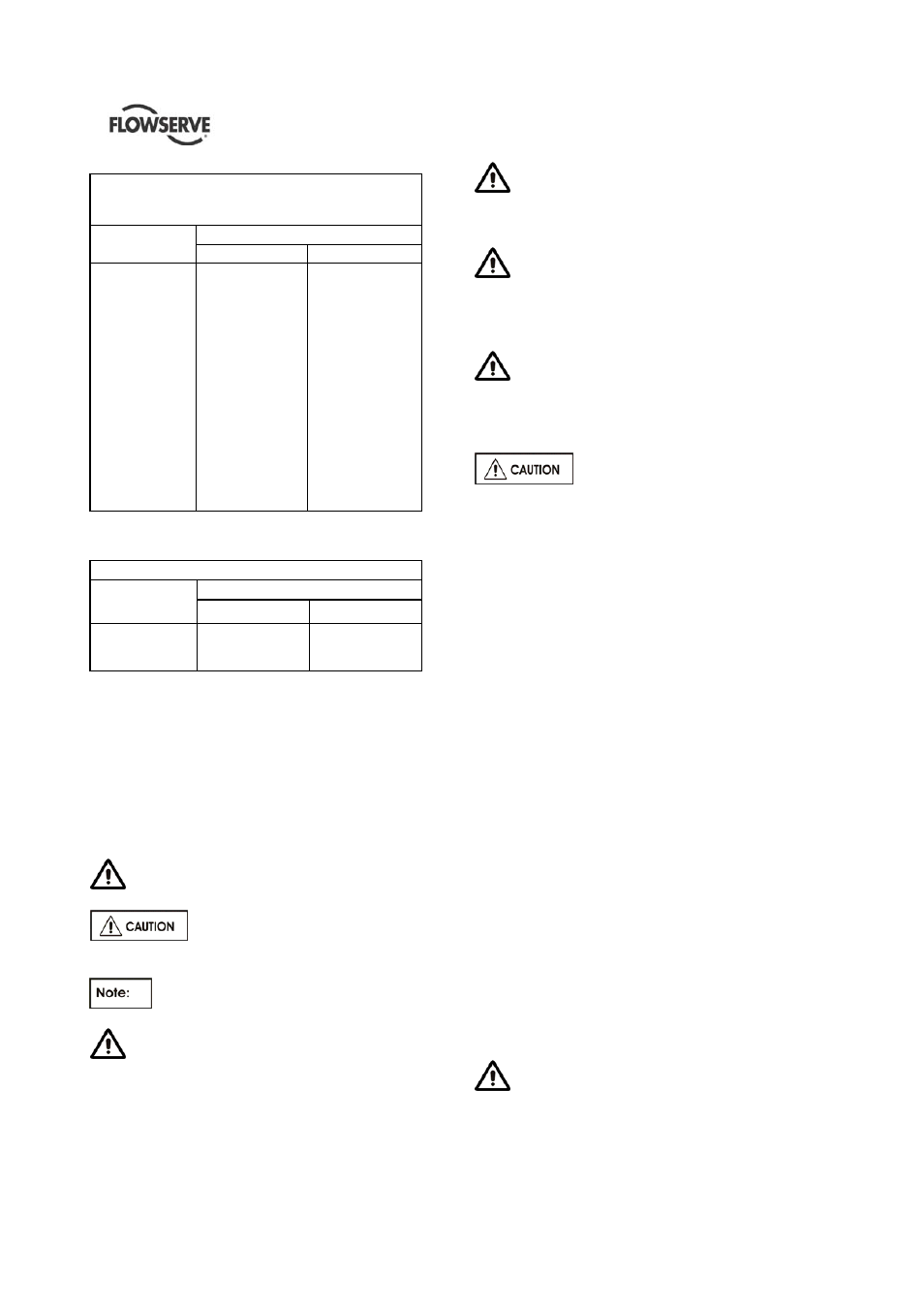
Bronze and Cast Iron Casing to Casing Cover
A536 60-40-18
A278 CL35
Stud Size
Torque Value
Nm (lbft)
3/8” 16UNC
1/2”13UNC
5/8” 11UNC
3/4” 10UNC
7/8” 9UNC
1” 8UNC
1 1/8” 8UN
1 1/4” 8UN
1 3/8” 8UN
1 1/2” 8UN
1 5/8” 8UN
1 3/4” 8UN
1 7/8” 8UN
2” 8UN
2 ¼” 8UN
2 ½” 8UN
15
29
59
108
177
265
392
589
785
1030
1324
1717
2109
2600
3777
5052
(11)
(22)
(43)
(80)
(130)
(195)
(289)
(434)
(579)
(759)
(976)
(1266)
(1555)
(1917)
(2785)
(3725)
Mechanical Seal to Casing Cover
Stud/Nut Size
Torque Value
Nm (lbft)
1/2”
5/8”
3/4”
44
88
169
32
65
125
Torque Values listed above are selected to achieve
the correct amount of pre-stress in the threaded
fastener. Maintenance personnel must ensure that
threads are in good condition (free of burrs, galling,
dirt, etc.) and that commercial thread lubricant NILS
Wega 2 containing molybdenum disulfide is used.
Torque should be periodically checked to ensure that
it is at the recommended value.
6.7 Disassembly
Refer to section 1.6, Safety, before dismantling
the pump.
Before dismantling the pump for
overhaul, ensure genuine Flowserve replacement
parts are available.
Refer to sectional drawings for part
numbers and identification.
Before attempting to disassemble the pump,
the pump must be isolated from the system, by
closing suction and discharge system valves,
drained of liquid and cooled, if pump is handling
hot liquid.
When the pump is handling “hot” liquid,
extreme care must be taken to ensure the safety
of personnel when attempting to drain pump. Hot
pumps must be allowed to cool before draining.
When the pump is handling “caustic” liquid,
extreme care must be taken to ensure the safety
of personnel when attempting to drain pump.
Protective devices of suitable protective materials
must be worn when draining pump.
Before attempting any maintenance work on
pumps in vacuum service, the pumps must be
isolated from suction and discharge system then
carefully vented to return pressure in pump
casing to atmospheric pressure.
Remove the pipe plug(s) from the
top of the bearing housing(s) and check to see
that oil rings are riding free on the pump shaft
and are not hung up. Failure to observe this
caution could result in damage to or destruction
of equipment.
6.7.1 Disassembly procedure
Care must be exercised in the dismantling operation
to prevent damages to internal parts of the pump. Lay
out all parts in the same order in which they are
removed for convenience at reassembly.
Protect all machined faces against metal-to-metal
contact and corrosion.
a) Switch off, lock and tag the motor circuit
breakers.
b) Switch off, isolate and tag all instrumentation and
monitoring equipment.
c) Close the pump suction valve. If discharge valve
has not already been closed this must be done
prior to dismantling.
d) Remove the pump coupling guard which is bolted
to the baseplate.
e) Remove the pump coupling spacer (Refer to
coupling instructions).
f) Drain the pump casing. This can be done by first
opening the vent connections situated at the top
of the casing and then opening the drains
situated at the bottom of the casing.
g) Drain the bearing housings of oil by removing the
drain plugs situated at the bottom of each bearing
housing. Remove oilers.
Use caution when draining hot oil from
bearing housing to prevent burns/injury to
personnel.