4 recommended spare parts (table 7), 5 tools required, 6 torques for fasteners – Flowserve MP1 Sier-Bath User Manual
Page 29: 7 renewal of clearances, 8 disassembly, 4 recommended spare parts
MP1 USER INSTRUCTIONS ENGLISH 26999958
– 10-12
Page 29 of 48
flowserve.com
c) Do not return parts without authorization.
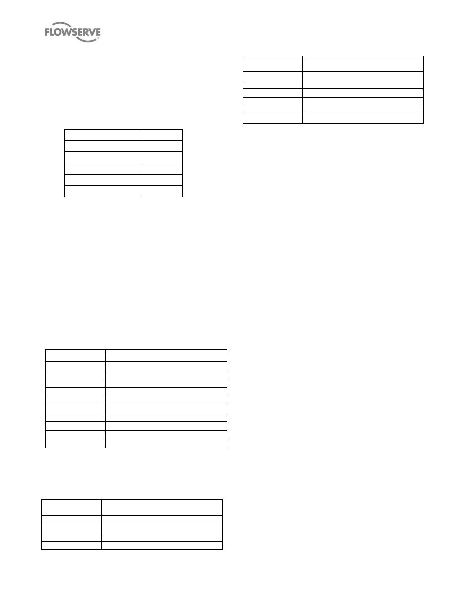
6.4 Recommended spare parts
Table 7
– Recommended spare parts
NAME OF PART
QTY.
Bearings
1 set
Oil Seals
1 set
Gaskets
1 set
Mechanical Seal
1/1 set
O Rings
1 set
Note: Refer to the Recommended Spare Parts list
furnished with the contract documentation for
specific part numbers.
6.5 Tools required
No special tools are required for assembly or
disassembly.
6.6 Torques for fasteners
Recommended torques for tightening the bolts and
screws on the pumps are given in the following tables.
6.6.1 Carbon steel bolts/nuts SAE grade 2
(1)
Table 8
– SAE grade 2 torques values
Thread Size (in.)
Recommended Torque Values (Ft-lbs)
3/8
17
1/2
40
5/8
80
3/4
135
7/8
150
1
210
1-1/8
300
1-1/4
420
1-3/8
550
1-1/2
720
(1)
These values are also suitable for 300 series stainless steel,
Monel, Inconel, Hastelloy, B & C and Alloy 20 fasteners.
6.6.2 High strength steel bolts/nuts SAE grade 5
Table 9
– SAE grad 5 torque values
Thread Size (in.)
Recommended Torque Values (ft.lbs)
3/8
27
1/2
65
5/8
125
3/4
225
Thread Size (in.)
Recommended Torque Values (ft.lbs)
7/8
365
1
545
1-1/8
675
1-1/4
950
1-3/8
1240
1-1/2
1430
6.7 Renewal of clearances
Twin screw pumps are used in a variety of applications
handling materials with a wide range of viscosities. As
such, it is difficult to predict at exactly what point screw
clearances are too large and the screws should be
repaired or replaced. In low viscosity or high pressure
applications, increased screw clearances may result in
an unacceptable loss in hydraulic performance. On the
other hand, in high viscosity or low pressure
applications, the same change in screw clearance may
result in very little change in pump hydraulic
performance. Since increased clearance can result in
lower pump performance, the flow capacity should be
the guiding parameter to define when the screw to
body bore clearance should be re-evaluated, and
compared to the value shown in the Engineering Data
section of this manual.
6.8 Disassembly
Note that replacements materials should be available
prior to disassembly to limit downtime. Refer to
sectional drawing shown in section 8 PARTS LIST
AND DRAWINGS of this manual and to the specific
sectional drawing and/or parts list applicable to your
pump.
6.8.1 Split bearing brackets
The split bracket provides a flanged joint between the
seal housing half and the bearing housing half of the
bracket. This joint allows full accessibility to the stuffing
box for both machining and mechanical seal
installation and maintenance. This is required for
cartridge mounted seals.
With split brackets it is not necessary to remove the
entire bracket to remove or inspect the seals. The
bracket can be split at the intermediate joint to gain full
access to the stuffing box, without disturbing the
primary body to bracket joint. It is critical that the
bracket halves be reassembled in the correct
orientation and with the dowel pins snugly fitted.
SPECIAL NOTE: These brackets are machined as
matched sets and as such are not interchangeable
with similar components on this or other units. The