Flowserve M Slurry User Manual
Page 36
M SLURRY USER INSTRUCTION ENGLISH 71569241 - 02/08
Page 36 of 60
®
More specialized equipment:
• Bearing pullers
• Bearing induction heater
• Dial test indicator
• C-spanner (wrench) - for removing shaft nut.
(If difficulties in sourcing are encountered, consult
Flowserve.)
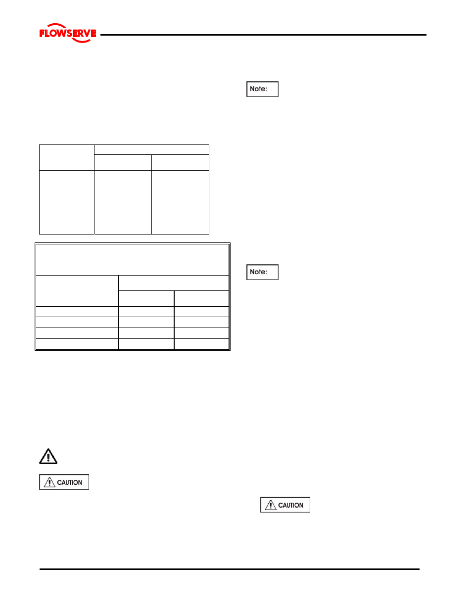
6.6 Fastener torques
Torque Nm (lb
yft)
Bolt size
Pump feet
fasteners
All other
fasteners
M 16 (⅝ in.)
M 20 (¾ in.)
M 24 (⅞ in.)
M 27 (1 in.)
M 30 (1⅛ in.)
M 36 (1⅜ in.)
M 42 (1⅝ in.)
M 48 (1⅞ in.)
170 (125)
340 (250)
590 (435)
770 (570)
1 100 (810)
1 840 (1 350)
2 000 (1 475)
2 240 (1 650)
84 (62)
165 (120)
285 (210)
375 (275)
540 (400)
900 (660)
1 410 (1 040)
2 060 (1 500)
TIGHTENING TORQUE
FOR STAINLESS STEEL STUDS
WITH LUBRICATED THREADS
THREAD SIZE
TIGHTENING TORQUE
Nm.
Ft. lbs.
M10x1.5 (3/8–16UNC)
13
10
M12x1.75 (1/2–13UNC)
27
20
M16X2 (5/8-11UNC)
60
45
M20x2.5 (¾-10UNC)
100
75
6.7 Renewal clearances
As wear takes place between the impeller and
wearplate the overall efficiency of the pump set will
decrease. To maintain optimum efficiency it is
recommended that the impeller be adjusted to
maintain the impeller axial clearance as detailed in
section 3.5, Table of Engineering Data. Typically
doubling the clearance can reduce performance by
5% depending on pump size and operating condition.
6.8 Disassembly
Refer to section 1.6, Safety, before dismantling
the pump.
Before dismantling the pump for
overhaul, ensure genuine Flowserve replacement
parts are available.
To disassemble the pump consult the sectional
drawings, see section 8, Parts list and drawings.
6.8.1 Rotating
Element
The following procedure is recommended for removing
and disassembling the rotating assembly.
Note that the replacement gaskets and similar
consumable materials should be available since they will
be required for reassembly.
a) Isolate motor and lock off electrical supply in
accordance with local regulations.
b) Isolate suction and discharge valves.
c) Remove
guards
d) Disconnect the coupling halves or remove belts
from sheaves.
e) Drain pump casing. Remove any auxiliary piping
if applicable.
f)
Disconnect stuffing box, cooling water and auxiliary
piping
.
g)
Drain the oil from the bearing frame [3122] if bearing
frame is being dismantled.
h)
Disconnect pump from piping and remove spool
pieces as necessary.
i) Remove pump from baseplate to work on bearing
frame.
For pumps fitted with an overhead motor
mount it is suggested that the motor be removed.
j) On severe duty pumps the suction cover may be
removed to work on the suction side wearplate,
impeller. Removal of pump from installation is not
necessary provided there is adequate room to
work. (ie removal of spool pieces from piping).
The remaining steps assume that the pump has been
removed.
6.8.1.1 Frames 1,2,3,&4
a) Place the sling around the bearing cartridge [3122]
and carefully take up the weight without straining the
casing. Refer to Section 3 to determine hoist and
sling requirements.
b) Loosen the set screws holding the deflector [2540]
on the shaft.
c) Release the thrust bearing housing [3240] hold down
bolts and jam nuts. While rotating the pump shaft
[2100] by hand, tighten the three jacking screws
evenly until the impeller [2200] lightly clamps the
stuffing box head [4100] in place. In the case of
expeller pumps the same will hold for the housing
[4110]. This will simplify withdrawal of the rotating
element from the casing.
Excessive clamping force could
damage bearing races.
Rotating the shaft helps to clear away solids which
may be trapped between the impeller and stuffing
box head.
d) Remove the bolts connecting the rear support foot