Floscan 9000-20B-1 GPS Interface System User Manual
Page 8
2/15/2007
7000-036-00M
FloScan Instrument Company, Inc.
Tel: (206) 524-6625 Fax: (206) 523-4961
3016 NE Blakeley Street, Seattle, WA 98105 Email: [email protected] Http://www.floscan.com
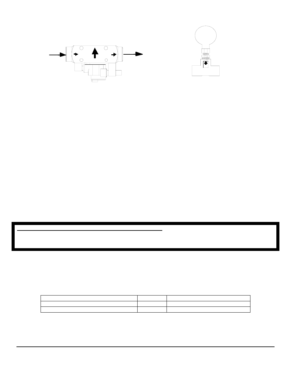
High-Flow
Pulsation
Damper
• Install sensor(s) with orientation arrows pointing UP Ï. Fuel must enter through the port marked IN or with an inward pointing
Î fuel flow arrow, and exit through the port marked OUT or with an outward pointing Î arrow.
• The sensor must be installed horizontally at a low point in the fuel system. When fuel exits the sensor it must travel up-hill
slightly. One or two inches of vertical rise is adequate, more is ok.
• The sensor must be installed downstream of, and protected by a screen, filter, or water separator. Sensors are tolerant of fine
debris. A coarse screen, (up to 800 microns) or water separator is all that is required.
• It is recommended that the sensor be installed between the fuel filter and fuel pump inlet. There should be at least twelve inches
of fuel hose, (more is ok) between the sensor and fuel pump inlet.
• If required, the pulsation damper must be installed horizontally, with its orientation arrow pointing up, (refer to fuel flow
schematics below).
• Minimize the number of 90º elbows and pipe fittings. Excessive use may create a high vacuum, fuel restricting pressure drop
across the fuel system. Whenever possible, use a large radius hose bend instead of elbows. Refer to the engine owner’s manual for
maximum fuel pump vacuum. A vacuum gauge can be used to confirm that the system is within limits.
• If swivel fittings are used, (JIC or SAE) their mating surfaces should be sealed with AP 50 Copper Conical Sealing Washers or
Flaretite Fitting Seals. Seals and sealing washers can be purchased through Fittings Inc. in Seattle, WA (206) 767-4670, 1-800-
552-0632, or a local hydraulic supply house.
CAUTION, DO NOT OVER TIGHTEN FLOW SENSOR FITTINGS. Over-tightening may crack the sensor’s body. Cracks
cause leaks and fuel leaks sometimes cause catastrophic explosions and fire. Assemble fittings with a Lubricating, Fuel Proof,
Non or Semi Hardening pipe thread sealant, designed for aluminum and stainless steel threads, (Loctite 567 or equivalent).
DO NOT USE TEFLON TAPE.
INSTRUMENT INSTALLATION
• Before cutting holes in your Instrument Panel, verify that the instrument will be installed approximately 12” away from the
compass, and in a shaded location out of direct sunlight. Mounting it within 12” of a compass may interfere with compass
operation. Direct sunlight may cause the LCD display to temporarily turn black due to heat.
Instrument Series
Cutout Size
Instrument Depth
5400(0), 5500(0)
3 1/16”
3” – Console Panel Thickness
7000(0), 8000(0), 9000(0), TwinScan
®
3 3/8”
2 ½” – Console Panel Thickness
Table 1
ARROW UP
Inlet
Outlet
233C SENSOR
- 9000-20B-2 GPS Interface System 9000-231-1 GPS Interface System 9000-231-11 GPS Interface System 9000-231-2 GPS Interface System 9000-231-21 GPS Interface System 9000-264-1 GPS Interface System 9000-264-2 GPS Interface System 9000-33C-1 GPS Interface System 9000-33C-11 GPS Interface System 9000-33C-2 GPS Interface System 9000-33C-21 GPS Interface System 90000-20B-1 GPS Interface System 90000-20B-2 GPS Interface System 90000-231-1 GPS Interface System 90000-23111 GPS Interface System 90000-231-2 GPS Interface System 90000-23121 GPS Interface System 90000-264-1 GPS Interface System 90000-264-2 GPS Interface System 90000-33C-2 GPS Interface System 90000-33C21 GPS Interface System 9900-231-1 GPS Interface System 9900-231-11 GPS Interface System 9900-20B-1 GPS Interface System 9900-20B-2 GPS Interface System 9900-231-2 GPS Interface System 9900-231-21 GPS Interface System 9900-264-1 GPS Interface System 9900-264-2 GPS Interface System 9900-33C-11 GPS Interface System 9900-33C-2 GPS Interface System 9900-33C-21 GPS Interface System 99000-20B-1 GPS Interface System 99000-231-1 GPS Interface System 99000-264-1 GPS Interface System Series 9000/90000 GPS Interface System 7000-20B-1 Multifunction Meter 7000-20B-1P Multifunction Meter 7000-20B-2 Multifunction Meter 7000-201-1 Multifunction Meter 7000-231-1 Multifunction Meter 7000-231-11 Multifunction Meter 7000-231-2 Multifunction Meter 7000-231-21 Multifunction Meter 7000-264-1 Multifunction Meter 7000-264-2 Multifunction Meter 7000-33C-1 Multifunction Meter 7000-33C-11 Multifunction Meter 7000-33C-2 Multifunction Meter 7000-33C-21 Multifunction Meter 70000-20B-1 Multifunction Meter 70000-20B-2 Multifunction Meter 70000-231-1 Multifunction Meter 70000-23111 Multifunction Meter 70000-231-2 Multifunction Meter 70000-23121 Multifunction Meter 70000-33C-1 Multifunction Meter 70000-33C11 Multifunction Meter 70001-231-1 Multifunction Meter 70001-231-2 Multifunction Meter 7200-20B-1 Multifunction Meter 7200-231-1 Multifunction Meter 7200-231-11 Multifunction Meter 7200-231-2 Multifunction Meter 7200-231-21 Multifunction Meter 72000-20B-1 Multifunction Meter 72000-231-2 Multifunction Meter 72000-23121 Multifunction Meter Series 7000/70000 Multifunction Meter