Wiring diagram, Flow sensor, Floscan instrument company, inc – Floscan 9000-20B-1 GPS Interface System User Manual
Page 17: Email
5/1/2006
9000-010-00E
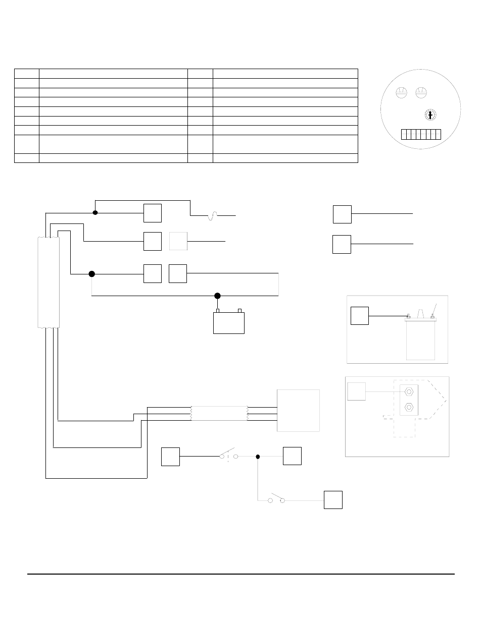
WIRING DIAGRAM
Series 9000(0) Multifunction Instrument with NMEA 0183 Input
Instrument Connection Harness
PIN
FUNCTION
PIN
FUNCTION
BLACK
RED
BACK OF INSTRUMENT
16 15 14
11
9
10
12
13
1
2
3
4
5
6
7
8
4
3
2
1
0
F
E
D
C
B
A
9
5
6
7
8
0
0
1 RED
Not
Connected,
(Twin Engine Applications)
9
RED + 12VDC
2
GREY GPH/MPG Switch
10
GREEN Totalizer Reset Switch
3
WHITE/YELLOW Not Connected 11
BLUE
Not
Connected
BLACK/ORANGE Battery Minus (–) *
4
ORANGE +12V Illumination
12
BLACK Battery Minus (–) or Minus Buss *
5
13
Black Totalizer, GPH/MPG Switches
6
WHITE Flow Sensor
14
BROWN Not Connected
GREEN/BLACK Battery Minus (–) or
Minus Buss *
7
15
WHITE/ORANGE Data (+) NMEA “B”
8
YELLOW Tachometer Input 16
VIOLET
Not
Connected
Single Sensor Installations
CABLE
CABLE
B
R
W
R
B
W
RED
WHITE
BLACK
6
9
5
BLACK
WHITE
RED
4
Flow
Sensor
GREEN
Totalizer
Reset Switch
(momentary ON)
10
BLACK
Coil
Distributor
YELLOW
8
+ 12VDC
8
YELLOW
Outboards
Inboard, I/O, Stern drive
Illumination Circuit (+ 12VDC)
12
BLACK/ORANGE
ORANGE
Illumination Circuit (- 12 VDC)
13
2
GREY
GPH/MPG switch
7
15
GREEN/BLACK
DATA (-)
DATA (+)
WHITE/ORANGE
1/2 amp fuse
To Switched
+ 12 VDC
Supply
+12VDC
BATTERY
-12VDC
*Ground refers to earth potential and is established by a
conducting connection through a conducting part of the
wetted hull, shaft or propeller. Battery Minus is called,
"Ground" only when it's electrically connected to, "Earth".
*
(Please see reverse s for twin engine installations)
FloScan Instrument Company, Inc.
Tel:
(206) 524-6625
Fax:
(206)
523-4961
3016 NE Blakeley Street, Seattle, WA 98105
Email:
Http://www.floscan.com
- 9000-20B-2 GPS Interface System 9000-231-1 GPS Interface System 9000-231-11 GPS Interface System 9000-231-2 GPS Interface System 9000-231-21 GPS Interface System 9000-264-1 GPS Interface System 9000-264-2 GPS Interface System 9000-33C-1 GPS Interface System 9000-33C-11 GPS Interface System 9000-33C-2 GPS Interface System 9000-33C-21 GPS Interface System 90000-20B-1 GPS Interface System 90000-20B-2 GPS Interface System 90000-231-1 GPS Interface System 90000-23111 GPS Interface System 90000-231-2 GPS Interface System 90000-23121 GPS Interface System 90000-264-1 GPS Interface System 90000-264-2 GPS Interface System 90000-33C-2 GPS Interface System 90000-33C21 GPS Interface System 9900-231-1 GPS Interface System 9900-231-11 GPS Interface System 9900-20B-1 GPS Interface System 9900-20B-2 GPS Interface System 9900-231-2 GPS Interface System 9900-231-21 GPS Interface System 9900-264-1 GPS Interface System 9900-264-2 GPS Interface System 9900-33C-11 GPS Interface System 9900-33C-2 GPS Interface System 9900-33C-21 GPS Interface System 99000-20B-1 GPS Interface System 99000-231-1 GPS Interface System 99000-264-1 GPS Interface System Series 9000/90000 GPS Interface System 7000-20B-1 Multifunction Meter 7000-20B-1P Multifunction Meter 7000-20B-2 Multifunction Meter 7000-201-1 Multifunction Meter 7000-231-1 Multifunction Meter 7000-231-11 Multifunction Meter 7000-231-2 Multifunction Meter 7000-231-21 Multifunction Meter 7000-264-1 Multifunction Meter 7000-264-2 Multifunction Meter 7000-33C-1 Multifunction Meter 7000-33C-11 Multifunction Meter 7000-33C-2 Multifunction Meter 7000-33C-21 Multifunction Meter 70000-20B-1 Multifunction Meter 70000-20B-2 Multifunction Meter 70000-231-1 Multifunction Meter 70000-23111 Multifunction Meter 70000-231-2 Multifunction Meter 70000-23121 Multifunction Meter 70000-33C-1 Multifunction Meter 70000-33C11 Multifunction Meter 70001-231-1 Multifunction Meter 70001-231-2 Multifunction Meter 7200-20B-1 Multifunction Meter 7200-231-1 Multifunction Meter 7200-231-11 Multifunction Meter 7200-231-2 Multifunction Meter 7200-231-21 Multifunction Meter 72000-20B-1 Multifunction Meter 72000-231-2 Multifunction Meter 72000-23121 Multifunction Meter Series 7000/70000 Multifunction Meter