Electrical, Floscan instrument company, inc – Floscan 9000-20B-1 GPS Interface System User Manual
Page 13
5/25/2006
4001-100-00J
ELECTRICAL
Series 5400(0)/5500(0)/56100/5800(0)/6500(0)/6600(0) AccuTroll & CruiseMaster,
All Multi Function Instruments, & TwinScan
®
SET UP
Wire & Switches: Use 18 AWG stranded wire on runs under 50’. For runs over 50’ use 16 AWG. Shielded wire is recommended
for all Diesel systems and suggested for Inboard & I/O gasoline systems. Always, “Ground” the wire shield or shield drain wires in
the engine room by connecting them to the bonding system or engine block. The double wiring harness for twin engine
Pulse/NMEA Diesel installations is included in all, (97/9800(0)) kits. FloScan suggests using J-Boxes, Terminal Blocks, and three
conductor cables between diesel sensors and instrument to make wiring easier.
Install Single Pole Single Throw (SPST) switches for Totalizer Reset, Port–Starboard Select, Engine Hours / Synchronizer, and
GPH / MPG, (switches are not included with kit). To determine which switch types are required for your system, refer to the table
below. All instruments except TwinScan
Tachometers require a totalizer reset switch.
FloScan Instrument Company, Inc.
Tel: (206) 524-6625 Fax: (206) 523-4961
3016 NE Blakeley Street, Seattle, WA 98105 Email: [email protected] Http://www.floscan.com
SYSTEM TOTALIZER
RESET
PORT/STBD
HOURS/
SYNCH
GPH/
MPG
MPG/
SYNCH
Twin Engine Systems
5400(0)
SPST or Momentary OFF
SPST NA
NA
NA
5500(0)/56100
SPST or Momentary OFF
SPST NA
NA
NA
5800(0)
SPST or Momentary OFF
NA NA
NA
NA
6500(0)/6600(0)
SPST or Momentary OFF
NA NA
NA
NA
65/6600(0) Cummins PT
SPST or Momentary OFF
SPST NA
NA
NA
7000/8000(0) Gasoline MFI
SPST or Momentary ON
SPST
SPST
NA
NA
71/8A00(0) MFI - Gasoline
EFI
SPST or Momentary ON
NA
NA
NA
NA
75/7600(0) Diesel MFI
SPST or Momentary ON
NA
NA
NA
NA
9000 Gasoline MFI
SPST or Momentary ON
SPST
SPST
SPST
NA
9A00(0) MFI - Gasoline EFI
SPST or Momentary ON
NA
NA
SPST
NA
95/96/97/9800(0)
SPST or Momentary ON
NA
NA
SPST
NA
TwinScan GPH Meter
SPST or Momentary ON
NA
NA
NA
NA
TwinScan Tachometer
NA
NA
NA
NA
NA
TwinScan GPH & Tachometer
SPST or Momentary ON
NA
NA
NA
SPST
NA = Not Applicable
Grounding: Each Black sensor wire must be connected directly to the Black, “Instrument Ground” wire. Use a single wire to
connect the Black wire junction to the battery’s negative terminal, or a ground buss.
Power: FloScan Instruments & sensors operate on 9 to 12 VDC. Voltages exceeding 16 VDC will damage equipment. 24 & 32
VDC systems must be reduced to 12 VDC. Two different types of voltage reducers are available through FloScan.
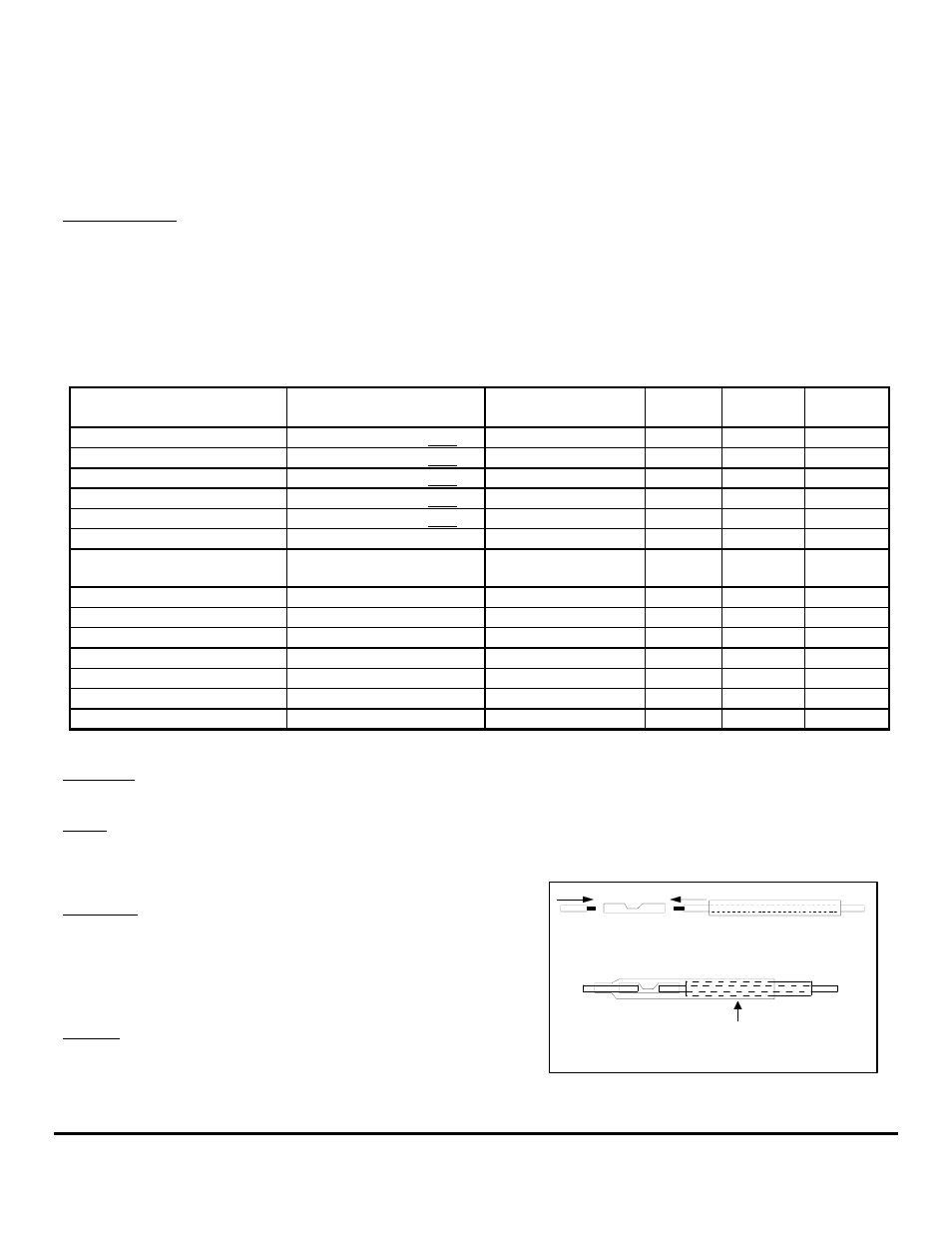
WIRE CONNECTIONS
1. Slide heat shrink tubing
over one wire.
2. Insert wire ends into butt splice.
3. Crimp butt splice.
4. Slide heat shrink tubing
over butt splice.
5. Apply heat.
HEAT
Installation: Connect wires one at a time and install heat shrink tubing
before proceeding to the next wire, (refer to diagram). Connect ground
wires first, (BLACK instrument ground wire to the BLACK sensor
wires). Connect this junction to the battery’s negative terminal or the
ground buss. Connect all other wires leaving the Red power wires for
last to prevent short circuits during installation.
Splicing: Splice or join individual wires per the diagram. Slide heat
shrink tubing over the splices to prevent shorts. Do not seal splices until
the installation is finished and has been tested.
- 9000-20B-2 GPS Interface System 9000-231-1 GPS Interface System 9000-231-11 GPS Interface System 9000-231-2 GPS Interface System 9000-231-21 GPS Interface System 9000-264-1 GPS Interface System 9000-264-2 GPS Interface System 9000-33C-1 GPS Interface System 9000-33C-11 GPS Interface System 9000-33C-2 GPS Interface System 9000-33C-21 GPS Interface System 90000-20B-1 GPS Interface System 90000-20B-2 GPS Interface System 90000-231-1 GPS Interface System 90000-23111 GPS Interface System 90000-231-2 GPS Interface System 90000-23121 GPS Interface System 90000-264-1 GPS Interface System 90000-264-2 GPS Interface System 90000-33C-2 GPS Interface System 90000-33C21 GPS Interface System 9900-231-1 GPS Interface System 9900-231-11 GPS Interface System 9900-20B-1 GPS Interface System 9900-20B-2 GPS Interface System 9900-231-2 GPS Interface System 9900-231-21 GPS Interface System 9900-264-1 GPS Interface System 9900-264-2 GPS Interface System 9900-33C-11 GPS Interface System 9900-33C-2 GPS Interface System 9900-33C-21 GPS Interface System 99000-20B-1 GPS Interface System 99000-231-1 GPS Interface System 99000-264-1 GPS Interface System Series 9000/90000 GPS Interface System 7000-20B-1 Multifunction Meter 7000-20B-1P Multifunction Meter 7000-20B-2 Multifunction Meter 7000-201-1 Multifunction Meter 7000-231-1 Multifunction Meter 7000-231-11 Multifunction Meter 7000-231-2 Multifunction Meter 7000-231-21 Multifunction Meter 7000-264-1 Multifunction Meter 7000-264-2 Multifunction Meter 7000-33C-1 Multifunction Meter 7000-33C-11 Multifunction Meter 7000-33C-2 Multifunction Meter 7000-33C-21 Multifunction Meter 70000-20B-1 Multifunction Meter 70000-20B-2 Multifunction Meter 70000-231-1 Multifunction Meter 70000-23111 Multifunction Meter 70000-231-2 Multifunction Meter 70000-23121 Multifunction Meter 70000-33C-1 Multifunction Meter 70000-33C11 Multifunction Meter 70001-231-1 Multifunction Meter 70001-231-2 Multifunction Meter 7200-20B-1 Multifunction Meter 7200-231-1 Multifunction Meter 7200-231-11 Multifunction Meter 7200-231-2 Multifunction Meter 7200-231-21 Multifunction Meter 72000-20B-1 Multifunction Meter 72000-231-2 Multifunction Meter 72000-23121 Multifunction Meter Series 7000/70000 Multifunction Meter