Troubleshooting – Floscan 5A20-20A-1 AccuTroll & CruiseMaster User Manual
Page 19
08/20/2004
4001-102-00I
FloScan Instrument Company, Inc.
Tel: (206) 524-6625
Fax: (206) 523-4961
3016 NE Blakeley Street, Seattle, WA 98105
Email:
Http://www.floscan.com
TROUBLESHOOTING
Series 5400(0)/5500(0)/56100 AccuTroll & CruiseMaster GPH/LPH Instrument
BEFORE
CALLING FOR ASSISTANCE, COMPLETE THESE TROUBLESHOOTING CHECKS AND RECORD YOUR
FINDINGS
.
TECHNICAL SUPPORT REQUIRES THIS INFORMATION BEFORE A RETURN AUTHORIZATION WILL BE ISSUED. IT
TAKES
ABOUT
20 MINUTES AND IS VERY IMPORTANT IN ANALYZING SYSTEM PROBLEMS
.
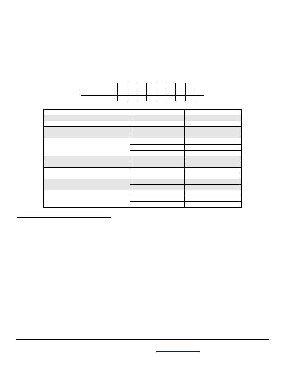
Before starting record the Instrument MODEL # ________________________ and all Switch settings.
ON
OFF
Switch
Settings 1 2 3 4 5 6 7 8 9
FAULT
PROBABLE CAUSE
SEE SECTION:
Blank LCD Display.
Wiring
Section I
No Back-Lighting.
Wiring/bulb failure
Section III
Low Totalizer Reading, more than 10%.
Calibration
Calibration sheet
Sensor orientation/failure
Installation Sheet
High Totalizer Readings, more than 10%.
Incorrect/defective sensor
Operations
Incorrect switch settings
Manual page
Suction
leak
Section
VI
Fluctuating GPH readings.
Suction leak
Section VI
Low RPM operation
Section VIII
No GPH or totalizer reading.
Wiring/Instrument failure
Section IV and V
Sensor orientation/failure
Installation sheet
No sensor readings.
Wiring
Section IV and V
Sensor failure
Section II
High sensor readings.
Suction leak
Section VI
Wrong switch settings
Calibration sheet
Sensor
orientation
Section
VII
I. INSTRUMENT HEAD DIAGNOSTIC TEST
1. Referring to the wiring diagram, verify that Instrument & Sensor(s) are wired correctly.
2. Verify that all wiring connections are tight and not corroded. Check continuity with an ohmmeter.
3. With power switched ON, measure voltage between the RED and BLACK wires,
(Take readings on the Instrument side of the butt splice connections).
__________VDC
The voltage reading should be between 12 and 14.5 VDC. Proceed to step 4 if it is, if not:
a. Check for voltage between the RED wire and another ground point.
b. If voltage is present, trace along the BLACK wire until its’ open connection is found.
c. If no voltage is present, trace the RED wire until its’ open connection is found.
4. With switched power ON slide, “Dip” switches 1-9 to the ON, or UP position. This places the
Instrument into diagnostic mode.
NOTE: If the LCD display is blank, verify that the totalizer reset switch, (Connected between the GREEN
wire and +12 volts) is in the ON position. Verify that 12 VDC is present between both switch
terminals and the Black wire. Next check the, “Green wire” fuse.
- 5220-264-1M AccuTroll & CruiseMaster 5232-231-1 AccuTroll & CruiseMaster 5232-231-1M AccuTroll & CruiseMaster 5232-264-1 AccuTroll & CruiseMaster 53040-20B-1 AccuTroll & CruiseMaster 53040-264-1 AccuTroll & CruiseMaster 53080-231-1 AccuTroll & CruiseMaster 53080-231-2 AccuTroll & CruiseMaster 53080-264-1 AccuTroll & CruiseMaster 5310-264-2 AccuTroll & CruiseMaster 53100-231-1 AccuTroll & CruiseMaster 53100-33C-1 AccuTroll & CruiseMaster 53100-33C11 AccuTroll & CruiseMaster 53160-231-1 AccuTroll & CruiseMaster 53160-23121 AccuTroll & CruiseMaster 53160-264-1 AccuTroll & CruiseMaster 5320-20B-1 AccuTroll & CruiseMaster 5320-20B-2 AccuTroll & CruiseMaster 5320-231-1 AccuTroll & CruiseMaster 5320-264-1 AccuTroll & CruiseMaster 5320-264-2 AccuTroll & CruiseMaster 5332-20B-1 AccuTroll & CruiseMaster 5332-20B-2 AccuTroll & CruiseMaster 5332-231-1 AccuTroll & CruiseMaster 5332-231-2 AccuTroll & CruiseMaster 5332-264-1 AccuTroll & CruiseMaster 5332-264-2 AccuTroll & CruiseMaster 5350-231-11 AccuTroll & CruiseMaster 53080-20B-1 AccuTroll & CruiseMaster 53160-23111 AccuTroll & CruiseMaster 54020-20A-1 AccuTroll & CruiseMaster 54020-20A-2 AccuTroll & CruiseMaster 54040-20A-1 AccuTroll & CruiseMaster 54040-20A-2 AccuTroll & CruiseMaster 5405-20A-1 AccuTroll & CruiseMaster 5405-20A-2 AccuTroll & CruiseMaster 54080-20A-1 AccuTroll & CruiseMaster 54080-20A-2 AccuTroll & CruiseMaster 5410-20A-1 AccuTroll & CruiseMaster 5410-20A-2 AccuTroll & CruiseMaster 5420-20A-1 AccuTroll & CruiseMaster 5420-20A-2 AccuTroll & CruiseMaster 55040-20B-1 AccuTroll & CruiseMaster 55040-231-1 AccuTroll & CruiseMaster 55040-231-2 AccuTroll & CruiseMaster 55040-264-1 AccuTroll & CruiseMaster 55040-264-2 AccuTroll & CruiseMaster 55080-20B-1 AccuTroll & CruiseMaster 55080-20B-2 AccuTroll & CruiseMaster 55080-231-1 AccuTroll & CruiseMaster 55080-231-2 AccuTroll & CruiseMaster 55080-264-1 AccuTroll & CruiseMaster 55080-264-2 AccuTroll & CruiseMaster 5510-20B-1 AccuTroll & CruiseMaster 5510-20B-2 AccuTroll & CruiseMaster 5510-201-2 AccuTroll & CruiseMaster 5510-231-1 AccuTroll & CruiseMaster 5510-264-1 AccuTroll & CruiseMaster 5510-264-2 AccuTroll & CruiseMaster 55100-231-1 AccuTroll & CruiseMaster 55100-231-2 AccuTroll & CruiseMaster 55160-20B-1 AccuTroll & CruiseMaster 55160-20B-2 AccuTroll & CruiseMaster 55160-231-1 AccuTroll & CruiseMaster 55160-231-2 AccuTroll & CruiseMaster 55160-23111 AccuTroll & CruiseMaster 55160-23121 AccuTroll & CruiseMaster 55160-264-1 AccuTroll & CruiseMaster 55160-264-2 AccuTroll & CruiseMaster 55161-231-1 AccuTroll & CruiseMaster 55161-231-2 AccuTroll & CruiseMaster 5520-20B-1 AccuTroll & CruiseMaster 5520-20B-2 AccuTroll & CruiseMaster 5520-231-1 AccuTroll & CruiseMaster 5520-231-2 AccuTroll & CruiseMaster 5520-264-1 AccuTroll & CruiseMaster 5520-264-1M AccuTroll & CruiseMaster 5520-264-2M AccuTroll & CruiseMaster 5520-264-2 AccuTroll & CruiseMaster 5532-20B-1 AccuTroll & CruiseMaster 5532-20B-2 AccuTroll & CruiseMaster 5532-231-1 AccuTroll & CruiseMaster 5532-231-1M AccuTroll & CruiseMaster 5532-231-2 AccuTroll & CruiseMaster 5532-231-2M AccuTroll & CruiseMaster 5532-231-11 AccuTroll & CruiseMaster 5532-231-21 AccuTroll & CruiseMaster 5532-264-1 AccuTroll & CruiseMaster 5532-264-2 AccuTroll & CruiseMaster 5550-231-1 AccuTroll & CruiseMaster 5550-231-2 AccuTroll & CruiseMaster 5550-231-11 AccuTroll & CruiseMaster 5550-231-21 AccuTroll & CruiseMaster 56100-234-1 AccuTroll & CruiseMaster 56100-33C-1 AccuTroll & CruiseMaster 56100-33C-2 AccuTroll & CruiseMaster 56100-33C11 AccuTroll & CruiseMaster 56100-33C21 AccuTroll & CruiseMaster 56500-33C-1 AccuTroll & CruiseMaster Series 5400 AccuTroll Series 5500/55000 CruiseMaster