Warning, Hot water coil piping precautions, Hot water coil piping – First Co UC-HW (without installed pump) User Manual
Page 3
Condensate drain lines must be installed
with adequate slope away from the unit
to assure positive drainage. Since the
drain pan is located on the suction side of
the blower, a negative pressure exists at
the drain pan and a minimum trap of 1-1/2
inches must be provided in the drain line
to assure proper drainage.
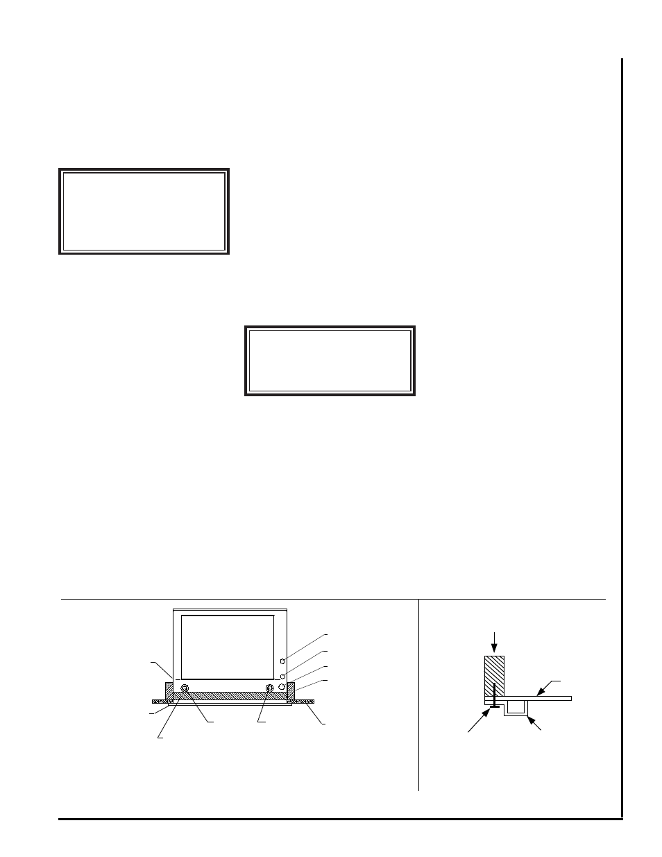
Figure 3
DETAIL OF WALL PANEL FRAME
INSTALLATION
INSTALLED UNIT
TOP VIEW
Figure 2
2 X 4
WALL STUD
SCREW
DRY WALL
WALL PANEL
FRAME
NOTE:
If a Condensate Overfl ow Shut-
off Switch, that is designed to be installed
in the drain line, is used in
place of a
secondary drain line, then the cut-off
switch should be located in the primary
drain line between the fan coil unit and
the P-trap.
HOT WATER COIL
PIPING PRECAUTIONS
• Flush all fi eld piping prior to connection
to remove all debris.
• Use wet cotton rags to cool valve bod-
ies when soldering.
• Open all valves (midway for hand
valves, manually open on motorized
valves) prior to soldering.
•When soldering to bronze or brass, heat
the piping while in the socket/cup and
begin introducing the solder when the
fl ux boils rapidly. Avoid direct fl ame into
the solder joint.
• Heat can only be applied to the cup of
the valve body for a minimal time before
damage occurs (even with the use of
wet rags.
• Avoid rapid quenching of solder joints as
this will produce joints of inferior quality.
• Connect all piping per accepted industry
standards and observe all regulations
governing installation of piping systems.
When all connections are complete the
system must be pressure tested. Repair
any solder joint leaks and gently tighten
any leaking valve packing nuts and pip-
ing accessories as required. Hydronic
systems are not designed to hold pres-
surized air and should only be tested
with water.
HOT WATER COIL PIPING
Refer to Flow Control Module instal-
lation instructions for proper pump instal-
lation, if used.
The hot water coil connections are 3/4
inch nominal (7/8” OD) copper. The hot
water supply to the fan coil should be on
the right when facing the fan coil upright
and from the front.
"T" Connections (at the water
heater)-
Water lines to and from the fan coil unit
must be taken from the horizontal con-
nection of the "T" fi ttings in the vertical hot
and cold water supply lines at the water
heater. This ensures that any air in the
system will be purged each time water is
used in the dwelling. See fi gure 4.
Isolation Valves -
Two valves are
recommended to be installed within the
circulating loop to permit servicing
of the system if required and to assist in
purging the system.
NOTE:
Hot water coil freeze protection
is available for applications where the
fan coil is located in ambient air locations
(attics, crawl spaces, etc.) or within struc-
tures that may be unoccupied during
freezing conditions. Consult the factory
for additional information.
OPERATION AND
MAINTENANCE
Pre-start Check
• Check that supply voltage matches
nameplate data.
• Ensure that the unit is properly
grounded.
• With power off, check blower wheel
set screw for tightness and ensure that
the blower wheels rotates freely and
quietly.
• Check that the refrigerant coil connec-
tions and piping have been leak checked
and insulated as required.
• Check that the water coil, valves and
piping have been leak checked and in-
sulated as required.
• Ensure that all air has been vented
from the hot water coil.
All piping between the water heater
and fan coil unit should be copper and
should not exceed 200 feet of total pip-
ing. It is recommended that 3/4” nominal
(7/8” OD) piping should be used on all
UC-HW units to prevent excessive head
pressure losses. (Consult the factory for
other piping applications.)
It is also recommended that all pip-
ing be adequately insulated to prevent
freezing when piping is run in an uncon-
ditioned space.
Solder Connections -
All copper
joints in the water lines must be made
with
low temperature - non lead
solder.
WATER
INLET
WATER
OUTLET
UC WALL PANEL FRAME
(PANEL ASSEMBLY IS
ORDERED SEPARATELY)
DRY WALL
2 x 4 WALL STUD
SUCTION LINE
LIQUID LINE
THERMOSTAT
WIRING
POWER
SUPPLY WIRING
CROSS MEMBER
(ON EDGE)
Note: Front edge of unit to
be fl ush with dry wall.
****** WARNING ******
On units with plastic drain
pans the drain connections
must be made hand tight
only.
****** WARNING ******
An expansion tank may be re-
quired if a back-fl ow preven-
ter is installed in the system.