First Co CLP-AQ (Less Than 30 Tall) User Manual
Page 4
and lines, open both valve number 1
and 2 and close the air bleed valve.
4) Switch the room thermostat to the
"Heat" position and raise the tem-
perature setting to a position approxi-
mately ten degrees above room tem-
perature.
NOTE: The door switch contacts
must be closed to operate the unit.
NOTE: The heating cycle has a
time delay relay to delay the blower
on a call for heat.
The pump should energize and begin
circulating the hot water through the
coil. If the pump is operating properly
and the water temperature in the water
heater has reached the set point, then
the hot water inlet at the fan coil unit
will be hot. If the pump is running but
hot water is not circulating, open the
air bleed valve long enough to purge
any remaining air from the hot water
lines and coil. This will allow the pump
to begin circulating hot water.
5)The water heater thermostat should
be adjusted so that the water tempera-
ture entering the hot water coil is as
close to 140 degrees as possible with
the system energized and operating
long enough for all temperatures to
stabilize.
MAINTENANCE
Fan
The fan should be inspected and
cleaned, in conjunction with mainte-
nance of the motor and bearings. It is
important to keep the wheel clean in
order to avoid imbalance and vibration.
Motor
Check motor connections to ensure
that they are secure and made in
accordance with the wiring diagram.
The blower motor should be cleaned
annually.
Coil
The coils must be kept clean, any
dust or other contaminants which ac-
cumulate on the heat transfer surfaces
interferes with the air flow and impairs
heat transfer. Inspect annually or
more frequently if required.
Filter
The air filter should be cleaned or
replaced every 30 days or more fre-
quently if severe conditions exist. Al-
ways replace the filter with the same
type as originally furnished.
Drain Piping
The drain should always be:
•
Connected or piped to an accept-
able disposal point sloped away
from the unit at least 1/8" per foot
•
Checked before summer operation
•
Periodically checked during sum-
mer operation
Preventative Maintenance
To achieve maximum performance
and service life of each piece of equip-
ment a formal schedule of regular
maintenance should be established
and maintained.
CHECK VALVE
REPLACEMENT
Disconnect electrical power before
servicing the unit.
To replace the internal check valve,
close the isolation valves and relieve
the water pressure within the heating
loop. Remove the four hex head
screws securing the pump motor to
the pump's volute and remove. The
check valve is located in the volute.
Rotate the check valve to release and
remove from the volute.
Reverse the above steps for rein-
stalling a check valve, however make
sure that the pump or volute has the
rubber o-ring in place before assem-
bling.
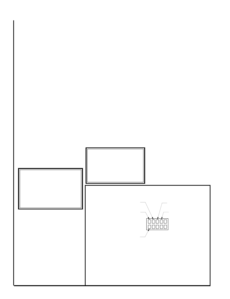
BRUSHLESS DC MOTOR CONNECTIONS
IF SO EQUIPPED
SEE WIRING DIAGRAM
Figure 2
Reverse the above steps for reas-
sembling the pump, however make
sure that the pump or volute has the
rubber o-ring in place before assem-
bling.
To replace the circulator pump,
close the isolation valves and relieve
the water pressure within the heating
loop. Disconnect the pump's 115 volt
power lines within the control box and
remove the four hex head screws se-
curing the pump motor to the pump's
volute.
PUMP REPLACEMENT
Disconnect electrical power before
servicing the unit.
****** WARNING ******
R-410a systems operate at
much higher pressures than
systems using former refriger-
ants. Use only equipment cer-
tified for use with R-410a.
**MAINTENANCE UPDATES**
For a current copy of the
Maintenance Program log on
to www.firstco.com and
look under "Product Informa-
tion"
C L G N
1 2 3 4 5
24VAC
Common
115 VAC
Neutral
Chassis Ground
115 VAC Line
Motor speed taps, 24VAC, see
wiring diagram on unit for
proper speed connections