Specifications (cont.) installation – Fire Magic 3100-51 Deluxe Grill & Grill Accessory Insulating Liner User Manual
Page 3
3
REV 0 - 1502100720
L-C2-465
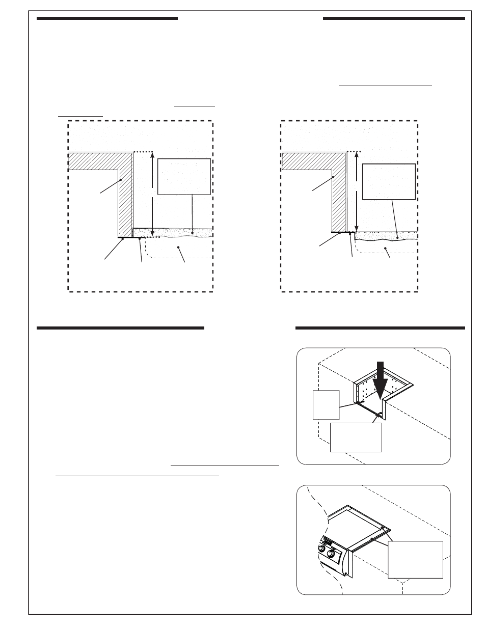
Fig. 3-3 Install insulating liner
Fig. 3-4 Install appliance into liner
SPECIFICATIONS (cont.)
INSTALLATION
1
1
/
2
"
hole
(gas)
1
1
/
2
"
electrical hole
(if applicable)
Appliance
hanger rests on
insulating liner
(sides and rear)
1. Install the insulating liner as shown in Fig. 3-3.
• If installing on a countertop with an irregular/textured
surface, a bead of silicone sealer rated for 400° or higher
may be needed.
• If the liner is being installed using method B, a 1
1
/
2
" hole
must be cut through the base (enclosure) to allow for proper
gas installation.
If applicable, a second 1
1
/
2
" hole must be cut to allow for
proper electrical installation.
S
ee
Fig. 3-3 for hole locations. Use the insulating liner holes
as guides. Remove knock-outs as needed.
• Holes exist at the rear of the liner; however, it is recommended
to use the front holes.
2. Install your appliance per your appliance owner's manual.
Important: Do not allow the appliance hanger to come in
contact with the countertop or any combustible
surface (
see
Fig. 3-4).
Substrate
When adding any substrate to the enclosure front wall (including tiles, stone, etc.), consider the following:
Substrate Behind Liner Flange
Substrate Alongside Liner Flange
C
C
Flush
(Countertop)
(Countertop)
Liner fl ange
(both sides)
Substrate
(includes tiles,
etc. at front of
enclosure)
Countertop
overhang
(if applicable)
Liner
Liner
Substrate
(includes tiles,
etc. at front of
enclosure)
Any additional substrate alongside the liner fl anges does
not need to be considered in Dim. C (see previous page).
Substrate + countertop "front to back" cutout
must equate to Dim. C (see previous page)
when the substrate sits fl ush behind the
liner fl anges.
Fig. 3-1
Fig. 3-2
Countertop
overhang
(if applicable)
TOP VIEW
TOP VIEW
Flush
Liner fl ange
(both sides)