Installation, Check barbecue fuel orifice size, Connect the gas supply to barbecue – Fire Magic Deluxe Drop In User Manual
Page 5: Install the flavor grid
5
Flavor grid
Flavor grid
leg
Burner
Perform the following checks before installing the barbecue:
CHECK BARBECUE FUEL ORIFICE SIZE
This barbecue comes from the factory confi gured for one
type of gas as marked on the label behind the barbecue
face plate. Each burner uses a different orifi ce depending
on the gas used in the barbecue. Please refer to Table 1 for
the correct orifi ce size.
1. Remove the cooking grids and fl avor grid from the
barbecue.
2. If the gas supply has been connected, make sure the
burner valve is in the OFF position. Then pull the knobs
from their stems. Use a Phillips screwdriver to turn the
face fastener screws counterclockwise to release the
face and remove it from the barbecue. Make sure to
retain the screws and fi nish washers until you are ready
to reattach the face.
Note: Carefully lift the face away from the frame. The
spark generators for the ignition system are
attached to the inside of the face panel. The spark
generator need not be detached, but the wires
must be unplugged from the generators before
the face is removed.
3. Using a fl at-blade screwdriver, pry the burner retaining
clip from rear wall of the barbecue frame (see
Fig. 5-1
).
Remove the burner by: 1) Pulling it to the front of
the barbecue, 2) Lifting the far end out of the notch,
3) Pulling the burner away from the manifold, taking
care not to lose the air shutter and spring, which may
become detached when the burner is removed.
4. Using a
3
/
8
" socket, remove orifi ce from the orifi ce holder
on the burner manifold and check the number stamped
on the face (see barbecue fuel orifi ce size in Table 1).
Repeat for each burner as necessary.
5. Replace the orifi ce with an orifi ce of the proper drill size as
listed in the PRODUCT DATA TABLE.
6. After checking the orifi ce drill size or replacing the orifi ce,
install the air shutter spring and the air shutter over the
orifi ce holder fi tting, between the burner and the burner
manifold, in the order and position shown in
Fig. 5-1
.
7. Replace the burners in the holding groove, ensuring that
the brass orifi ce and orifi ce holder fi ttings project deeply
into the burners. Replace the burner retaining clips.
WARNING:
It is critical to the continued safe operation of
the burner that it be properly aligned with the
orifi ce, as indicated above.
CONNECT THE GAS SUPPLY TO BARBECUE
CAUTION:
Use only stainless steel fl ex connectors that
are C.S.A. listed.
INSTALLATION
WARNING:
A rubber or plastic connector will rupture
or leak, resulting in an explosion or
serious injury if used inside the barbecue
enclosure.
1. Make sure that the gas supply is turned OFF. Then
connect the
1/2
" (1.27 cm) pipe adapter fi tting supplied
with the stainless steel fl ex connector to the gas
supply stub. Use pipe joint compound that is resistant
to all gasses or Tefl on tape on all male pipe fi ttings
and tighten securely. Do not use pipe joint compound
to connect brass fl are fi ttings.
2. Lower the barbecue into place, making sure not to
pinch or kink the gas connector. The unit may be
supported above the counter by blocks inserted under
the fl anges at each side of the frame (
Fig. 5-2
).
3. If the pipe does not come up against the front wall, it
can easily be run along the enclosure fl oor and turned
up to rise within 5" (12.7 cm) of the countertop, tight
against the front wall (leaving space only to connect
fi ttings).
4. Connect the fl ex connector to the fl are fi tting on the
manifold inlet. Support the manifold inlet fi tting with
a wrench to avoid applying excessive torque to the
manifold assembly while tightening this connection
securely. Do not use pipe compound on fl are fi ttings.
Make sure the barbecue burner valve is in the OFF
position. Turn the gas supply on. Then carefully check all
gas connections for leaks with a brush and soapy water
before lighting. NEVER USE A MATCH OR OPEN FLAME
TO TEST FOR LEAKS.
5. Refer to the AIR SHUTTER ADJUSTMENT instructions
before replacing barbecue face and knobs.
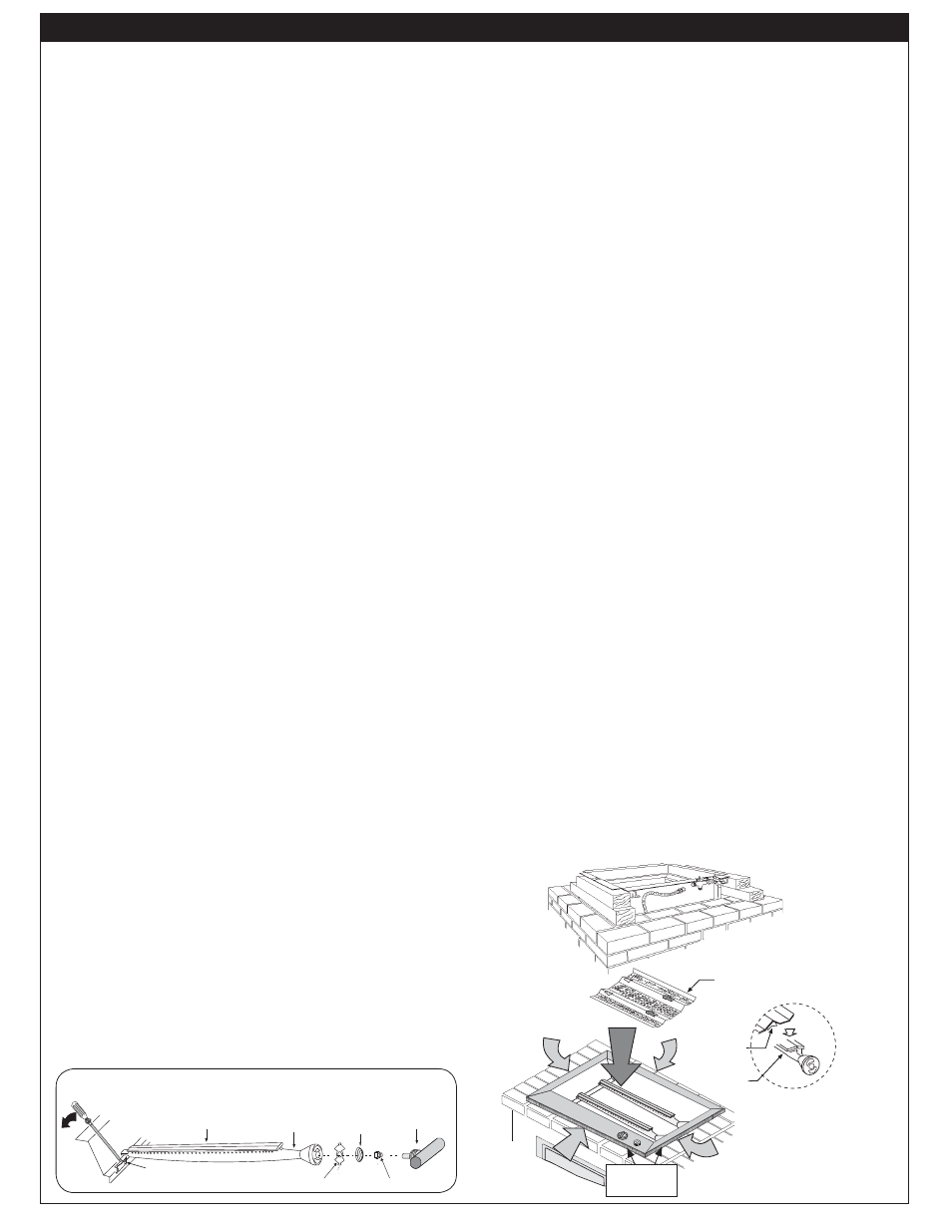
INSTALL THE FLAVOR GRID
Place the fl avor grid directly on the burners (
Fig. 5-3
).
Center the grid over the burners with the open side up.
This allows heat from the burners to be evenly distributed
throughout the cooking area. The fl avor grid heats and cools
quickly, making your Fire Magic barbecue very responsive
to the changes you specify in grill temperature.
The fl avor grid is made of stainless steel and is rust
resistant. It may be cleaned with standard oven cleaners.
Fig. 5-2
AIR SHUTTER
BURNER
MANIFOLD WITH
ORIFICE HOLDER
BURNER
ORIFICE
SPRING
BURNER NECK
BURNER CLIP
Fig. 5-1
Burner
Burner neck
Spring
Burner manifold
with orifi ce holder
Air shutter
Orifi ce
Burner clip
Fig. 5-3
Important: Keep ventilation
openings clear.
Ventilation
openings
Ventilation
air
REV 3 - 1406200825
L-C2-018