Installation requirements, Correct, Incorrect – Fire Magic Aurora Multi-Housing Built-In Grill A430i-1E1(N,P)-01 User Manual
Page 7
7
INSTALLATION REQUIREMENTS
This grill is designed for outdoor use only. DO NOT use this grill under unprotected fl ammable surfaces.
DO NOT use this grill inside a building, garage, enclosed area, or an unprotected covered area (see
EXHAUST REMOVAL below). DO NOT use this grill in or on a recreational vehicle or boat.
Important:
The grill must have a minimum of 18" (45.7 cm) right, left, and back clearance from unprotected
combustible construction. If installing this grill in a combustible surround, the correct R. H. Peterson
insulating liner must be used.
The control panel MUST remain removable for servicing
(see PARTS LIST).
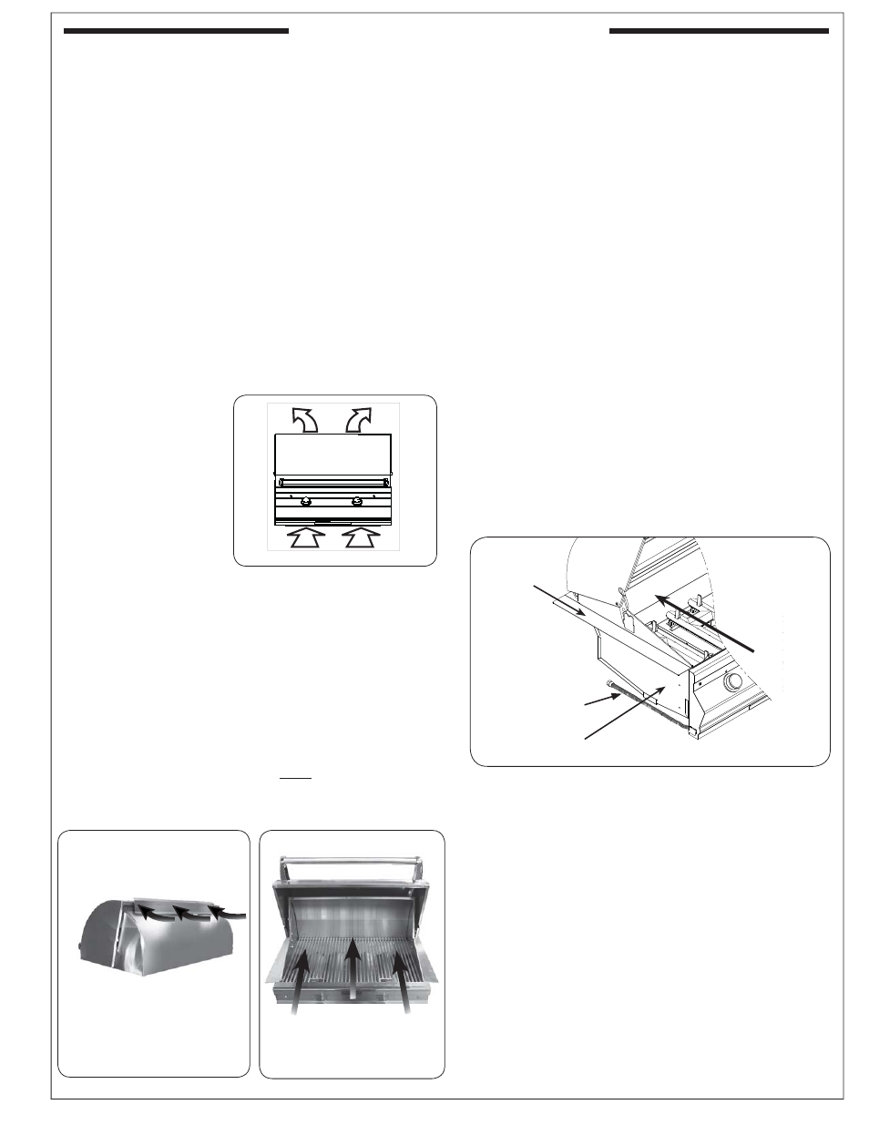
ENSURING PROPER COMBUSTION AIR AND
COOLING AIRFLOW
Proper airfl ow (Fig. 7-1) MUST be maintained for the
grill to perform as it was designed. If airfl ow is blocked,
overheating and poor combustion will result. Do not
block the 1" (2.5 cm) front air inlet along the bottom of
the control panel or more than 75% of the cooking grid
surface with pans or griddles.
Note: The 1" (2.5 cm)
front air space
a l s o a l l o w s
access to the
drip tray.
EXHAUST REMOVAL
If installed or used under a patio roof, the cooking grid
area must be fully covered by an exhaust hood with a vent.
An exhaust fan with a rating of 1,000 CFM (cubic feet per
minute) (472 liters per second) or more may be necessary
to effectively remove smoke and other cooking by-products
from the area under the hood. Fire Magic Vent Hoods
are available to meet this requirement. This grill must
not be used under unprotected overhead combustible
construction. THIS UNIT MUST NOT BE LOCATED IN
A FULLY ENCLOSED AREA OF ANY KIND.
GAS-SUPPLY PLUMBING REQUIREMENTS
For natural gas or a household propane system, rigid
1
/
2
"
(1.3 cm) or
3
/
4
" (1.9 cm) black steel pipe or local code-
approved pipe is required to conduct the gas supply to
the unit. Contact your local gas supplier. Connect this
pipe to the required C.S.A.-approved stainless-steel fl ex
connector (attached). An NPT adapter has been provided
for
1
/
2
" pipe. DO NOT use a rubber hose within the grill
enclosure. Apply only joint compounds that are resistant
to all gasses to all male pipe fi ttings except fl are fi ttings.
Make sure to tighten every joint securely.
Note: If
1
/
2
" (1.3 cm) pipe is used with natural gas,
it should be no longer than 20' (6.1 meters).
Important:
An external valve (with a removable
key) in the gas line is necessary for
safety when the grill is not in use. It also
provides for convenient maintenance.
CAUTION: Wind blowing into or across the rear
oven lid vent (Fig. 7-2) can cause
poor performance and/or dangerous
overheating. Orient the grill so that the
prevailing wind blows toward the front of
the grill (Fig. 7-3).
CAUTION: To prevent dangerous overheating, the rear
of the unit must have a minimum clearance
of 4" (10.2 cm) from any backsplash/wall.
GAS SUPPLY AND MANIFOLD PRESSURES:
For natural gas - normal 7" (17.78 cm) water column
(w.c.), minimum 5" (12.7 cm), maximum 10
1
/
2
" (26.7
cm). For propane gas - normal 11" w.c., minimum 10"
(25.4 cm), maximum 13" (33 cm).
REV 0 - 1307081445
L-C2-414
Fig. 7-1
- Ventilation diagram
Left-side
hanger
Fig. 7-4
Flex connector
Left-side
support wall
Orient grill
so prevailing
wind blows
this way.
Fig. 7-3
CORRECT
PLACE GRILL SO PREVAILING
WIND BLOWS TOWARD FRONT
OF GRILL
Equipped wind defl ector will
improve performance of grill.
However, you must still protect
rear oven from prevailing wind.
Rear oven lid vent
INCORRECT
Fig. 7-2