FiberPlex FOM-1090 User Manual
Page 8
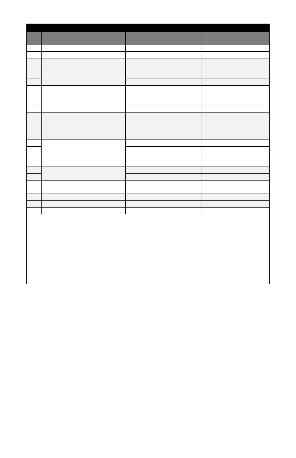
Pinouts (X.21 with adapter cable information)
Pin
FOM‐1091
(DCE) Direction
FOM‐1090
(DTE) Direction
X.21 Configuration
DB‐15 Pin
1
Chassis Ground
1
7
Signal Ground
8
2
Out
In
Send Data A (SD) (V.11)
2
14
Send Data B (SD\) (V.11)
9
3
In
Out
Receive Data A (RD) (V.11)
4
16
Receive Data B (RD\) (V.11)
11
4
Out
In
Request To Send A (RTS) (V.11)
‐
19
Request To Send B (RTS\) (V.11)
‐
5
In
Out
Clear To Send A (CTS) (V.11)
‐
13
Clear To Send B (CTS\) (V.11)
‐
20
Out
In
IND A (TR) (V.11)
3
23
IND B (TR\) (V.11)
10
6
In
Out
DM A (V.11)
‐
22
DM B (V.11)
‐
24
Out
In
Terminal Timing A (TT) (V.11)
‐
11
Terminal Timing B (TT\) (V.11)
‐
8
In
Out
CON A (V.11)
5
10
CON B (V.11)
12
15
In
Out
BT A (ST) (V.11)
7
12
BT B (V.11)
14
17
In
Out
ST A (V.11)
6
9
ST B (V.11)
13
18
‐
‐
‐
‐
25
‐
‐
‐
‐
21
‐
‐
‐
‐
Notes:
The X.21 ST signal will be routed through the FOM labeled as RT (pins 17 & 9) as this would be the
equivalent clock for conversion to other interfaces. The BT signal is routed through on the ST signal (pins 15
& 12). The BT signal may not be present on some X.21 interfaces.
The FOM signal TT is available on the DB25 connector, but there is no equivalent signal assigned to the X.21
interface. Some X.21 interfaces support a companion clock sourced from the same end as the TD signal,
using the BT pins for that clock. The TT signal may be used for that clock in those cases.
The FOM signals RS, CS, and DM are available on the DB25 connector, but there are no equivalent signals
assigned to the X.21 interface. These signals may alternately be used for the CONTROL and INDICATION
signals to allow for adapting flow control to a non‐X.21 interface at the opposite end.