Configuring dip switch parameters – FiberPlex FOM-1090 User Manual
Page 17
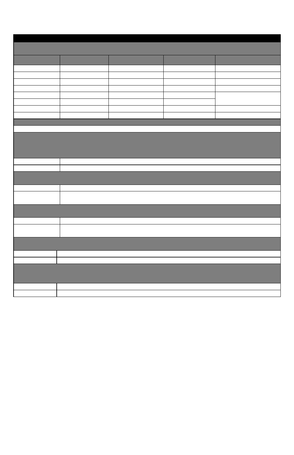
Configuring DIP Switch Parameters
(All default settings are OFF with exception of interface selection.)
Switch 1
Switches 1.1, 1.2, and 1.3: Interface Configuration
(The rear panel INTF led will indicate the current interface setting.)
Interface
Switch 1.1
Switch 1.2
Switch 1.3
INTF LED
X.21
Off
On
On
1 Flash
TIA‐232
On
On
Off
2 Flashes
V.35
On
Off
Off
3 Flashes
TIA‐449
On
Off
On
4 Flashes
TIA‐530 (422)
Off
On
Off
5 Flashes
Default (TIA‐530)
Off
Off
Off
TIA‐530A
Off
Off
On
6 Flashes
Disabled
On
On
On
Solid Red
Switch 1.4: No Function
Switch 1.5: Data Invert
Changes the MARK condition for use with MIL‐STD type interfaces. The idle state for some MIL‐STD interfaces is the
opposite of TIA and this setting allows the conversion from those MIL signals to TIA or between opposite state MIL
interfaces when this switch is ON.
Off
Negative MARK
On
Positive MARK
Switch 1.6: Data Regeneration A (FOM‐1091 ONLY)
Enables FOM‐1091 auto or manual adjustment for regeneration of TD signal to DCE
Off
Normal operation
On
Enables various modes of TD out signal regeneration using ST signal from DCE in conjunction with
switch 1.7.
Switch 1.7: Data Regeneration B (FOM‐1091 ONLY)
Enables FOM‐1091 auto or manual adjustment for regeneration of TD signal to DCE.
Off
Normal operation
On
Enables various modes of TD out signal regeneration using ST signal from DCE in conjunction with
switch 1.6.
Switch 1.8: Invert Send Timing Out (FOM‐1090 only)
Inverts ST signal out of FOM‐1090.
Off
No inversion
On
ST out is inverted
Switch 1.8: Data Regeneration C (FOM‐1091 only)
Changes TD out relationship to ST in at FOM‐1091 when using Data Regeneration Switch. No function if Switch 1.6 and
Switch 1.7 are off
Off
TD out transitions on rising edge of ST in
On
TD out transitions on falling edge of ST in