FiberPlex FOM-1090 User Manual
Page 7
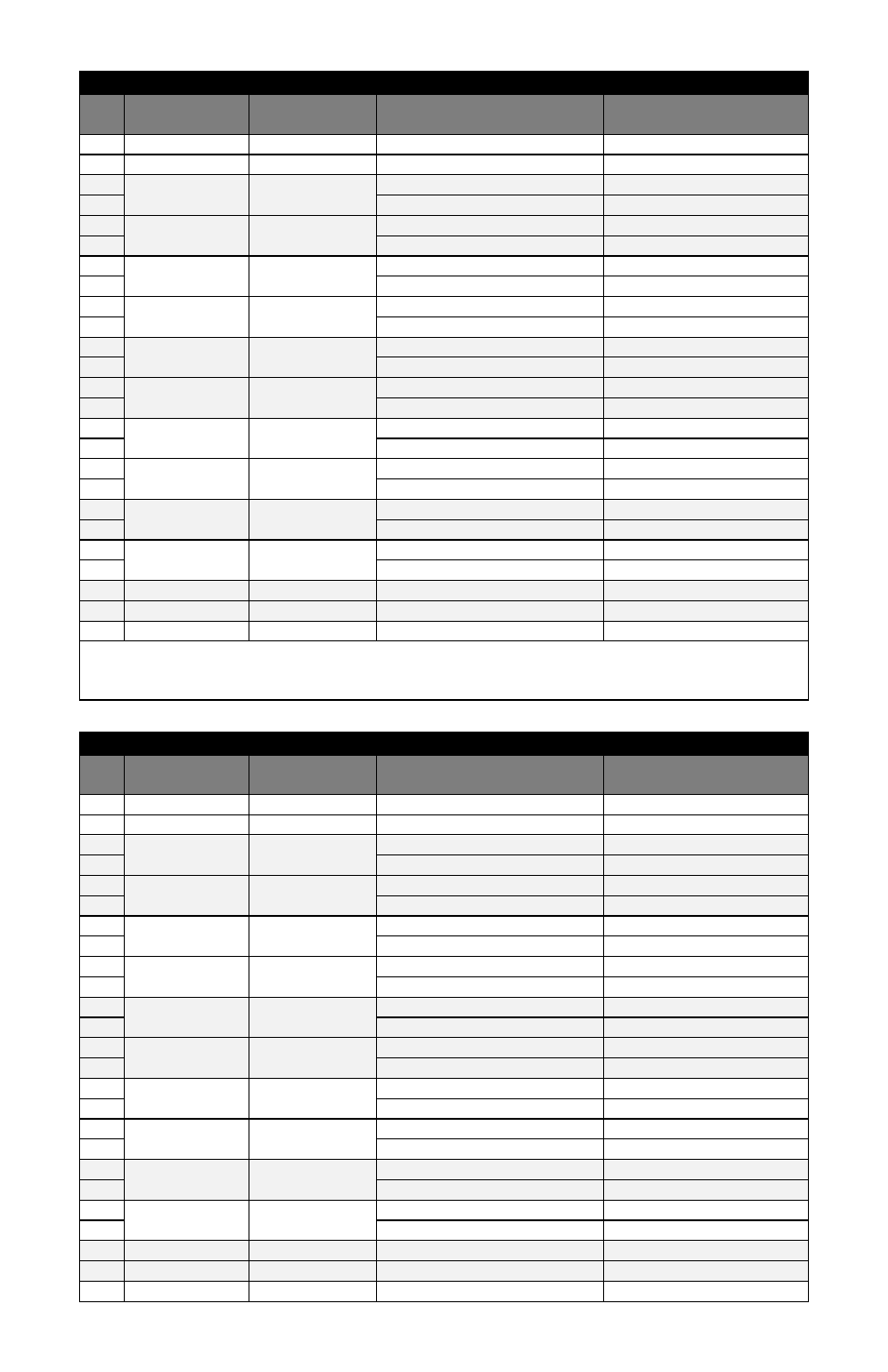
Pinouts (TIA‐449 with adapter cable information)
Pin
FOM‐1091
(DCE) Direction
FOM‐1090
(DTE) Direction
TIA‐449 Configuration
DB‐37 Pin
1
Chassis Ground
1
7
Signal Ground
19, 20, 37
2
Out
In
Send Data A (SD) (V.11)
4
14
Send Data B (SD\) (V.11)
22
3
In
Out
Receive Data A (RD) (V.11)
6
16
Receive Data B (RD\) (V.11)
24
4
Out
In
Request To Send A (RTS) (V.11)
7
19
Request To Send B (RTS\) (V.11)
25
5
In
Out
Clear To Send A (CTS) (V.11)
9
13
Clear To Send B (CTS\) (V.11)
27
20
Out
In
Terminal Ready A (TR) (V.11)
12
23
Terminal Ready B (TR\) (V.11)
30
6
In
Out
Data Set Ready A (DSR) (V.11)
11
22
Data Set Ready B (DSR\) (V.11)
29
24
Out
In
Terminal Timing A (TT) (V.11)
17
11
Terminal Timing B (TT\) (V.11)
35
8
In
Out
Receiver Ready A (RR) (V.11)
13
10
Receiver Ready B (RR\) (V.11)
31
15
In
Out
Send Timing A (ST) (V.11)
5
12
Send Timing B (ST\) (V.11)
23
17
In
Out
Receive Timing A (RT) (V.11)
8
9
Receive Timing B (RT\) (V.11)
26
18
Out
In
Local Loopback (LL) (V.10)
10
25
In
Out
Test Mode (TM) (V.10)
18
21
Out
In
Remote Loopback (RL) (V.10)
14
Note: For best signal performance do not tie pin 20 (Receive Common), pin 37 (Send Common), or pin 19
(Signal Ground) together at the DB‐37 connector. Bring all three pins back on individual conductors to pin 7 of
the DB‐25 and tie them together there.
Pinouts (TIA‐232; TIA‐574 with adapter cable information)
Pin
FOM‐1091
(DCE) Direction
FOM‐1090
(DTE) Direction
TIA‐232 Configuration
TIA‐574 DB‐9 Pin
1
Chassis Ground
‐
7
Signal Ground
5
2
Out
‐
In
‐
TD (V.28)
3
14
‐
‐
3
In
‐
Out
‐
RD (V.28)
2
16
‐
‐
4
Out
‐
In
‐
RTS/RS (V.28)
7
19
‐
‐
5
In
‐
Out
‐
CTS/CS (V.28)
8
13
‐
‐
20
Out
‐
In
‐
DTR/TR (V.28)
4
23
‐
‐
6
In
In
Out
Out
DSR/DM (V.28)
6
22
RI/IC (V.28)
9
24
Out
‐
In
‐
TT (V.28)
‐
11
‐
‐
8
In
‐
Out
‐
DCD/RR (V.28)
1
10
‐
‐
15
In
‐
Out
‐
ST (V.28)
‐
12
‐
‐
17
In
‐
Out
‐
RT (V.11)
‐
9
‐
‐
18
Out
In
LL (V.28)
‐
25
In
Out
TM (V.28)
‐
21
Out
In
RL (V.28)
‐