Normal – ESI M4U User Manual
Page 4
ESI Miditerminal M4U
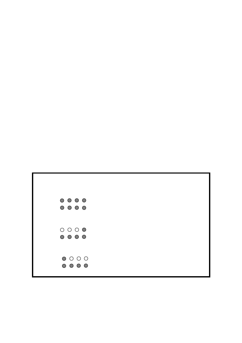
2) THRU Mode 1: Input and Output ports will be matched by 1:1. For example,
the MIDI data from Input 2 directly goes to Output 2. All LEDs will be turned
on. After 2~3 seconds, LED will be turned off again. The PWR/THRU LED
will become green color.
3) THRU Mode 2: The MIDI data from Input 4 goes to Output 1~4. LED Display
Input 4 and Output 1~4 would be turned on. After 2~3 seconds, Output 1~4 will
be turned off (Input 4 remains turned on). Output LED will be lit by the signal.
The PWR/THRU LED will become green color.
4) THRU Mode 3: The MIDI data from Input 1 goes to Output 1~4. LED Display
Input 1 and Output 1~4 would be turned on. After 2~3 seconds, Output 1~4 will
be turned off (Input 1 remains turned on). Output LED will be lit by the signal.
The PWR/THRU LED will become green color.
* Three kinds of THRU modes are changed in sequence whenever the button is
pushed in.
Function
LED signal display
Normal
Basic MIDI interface
THRU 1
I/O port matching (1:1)
All LEDs will be turned on
After 2~3 seconds, LED will be turned off
again, flickering according to the signal.
THRU 2
In 4 -> All MIDI Outputs
In 4, Out 1~4 display will be turned on
After 2~3 seconds, Out 1~4 LED will be turn
off again (In 4 remains turned on), flickering
according to the signal.
THRU 3
In 1 -> All MIDI Outputs In 1, Out 1~4 display will be turned on
After 2~3 seconds, Out 1~4 LED will be turn
off again (In 1 remains turned on), flickering
according to the signal.
6