EM Acoustics MSE-159SP self-powered fullrange loudspeaker User Manual
Page 18
Page 18 of 25
MSE-159SP User Manual
v1.0 May 2012
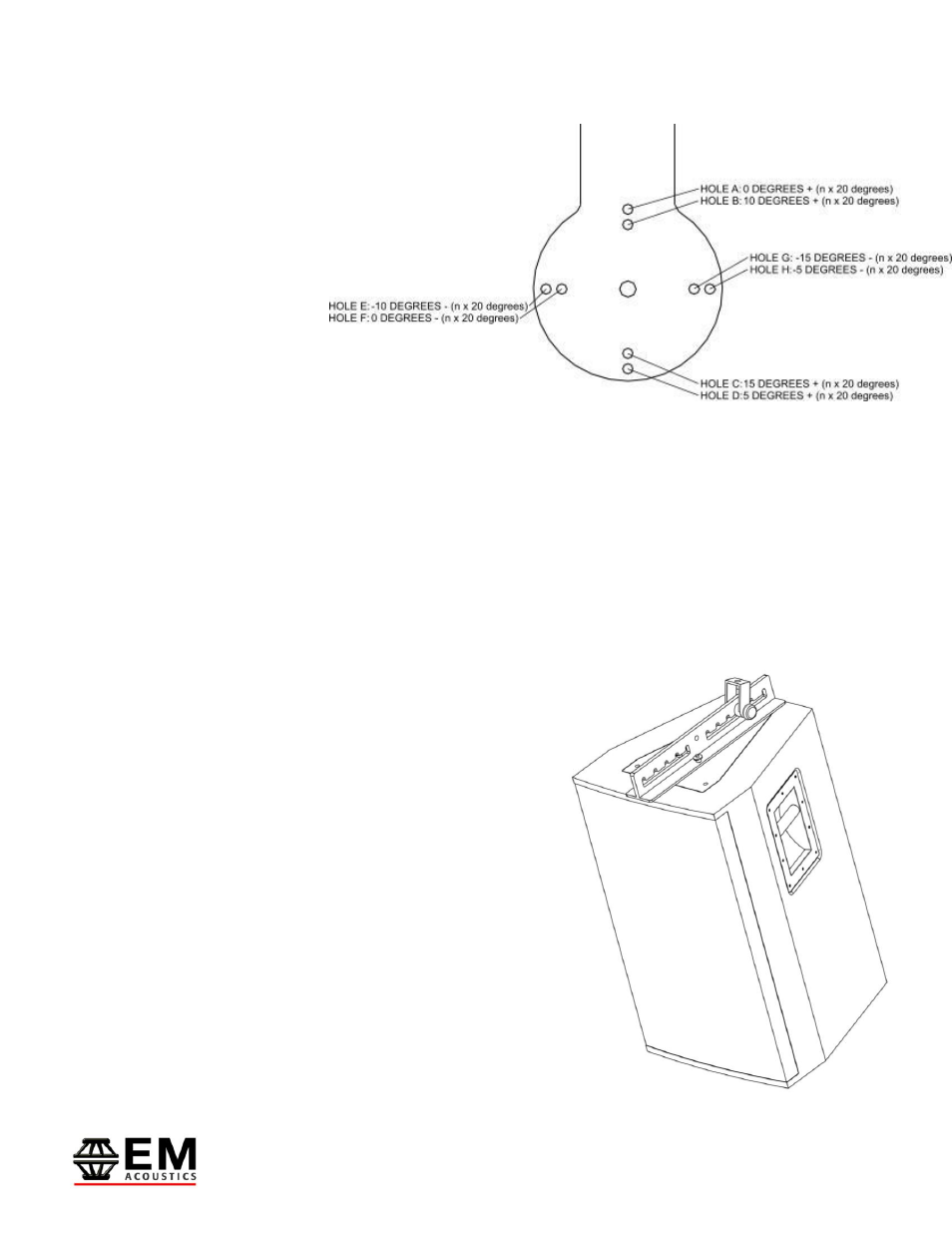
As shown in
the
diagram opposite, as
you rotate the inner
yoke different holes will
be available to secure
with the pins. Select
the desired angle, and
lock in place with the
attached ball-lock pin.
To give further explanation, Holes A-D are used for down-tilt and holes E-H are used for
up-tilt. Hole A is used for 0-degree angle, and also for multiples of 20 degrees above this
(20, 40, 60, 80 degree down-angle). Hole B is used for 10 degrees, and multiples of 20
degrees above this (10, 30, 50, 70, 90 degree down angle). Similarly, Hole C is used for 5
degrees and multiples of 20 degrees above this (5, 25, 45, 65, 85) and Hole D is used for
15 degrees and multiples of 20 degrees above (15, 35, 55, 75). Holes E-H apply in a
similar way for up-tilt.
5.5 - Attachment of the VFA-159 variable flying bracket
To attach the bracket, first release the two ball-lock
pins from the base of the bracket. Position the
bracket over the top or bottom of the loudspeaker (it
can be flown either way up) and insert the bosses on
the bottom of the bracket into the keyholes on the
enclosure’s flying plate. Slide the bracket to the rear
of the enclosure until the two ¼” diameter locking-pin
holes line up. Insert the two ball-lock pins into the
holes to lock the bracket in place. IMPORTANT: DO
NOT ATTEMPT TO LIFT THE LOUDSPEAKER
WITHOUT BOTH BALL-LOCK PINS IN PLACE.
Finally, attach a hook-clamp to the sliding mounting
point and secure the mounting point bolt through the