0 installation – Electro-Chemical Devices (ECD) CA6 Filtration Unit User Manual
Page 7
7
2.0 INSTALLATION
2.1 Unpacking and Inspection
Your Electro-Chemical Devices instrument has been carefully packaged to
protect it from damage during shipment and dry storage. Upon receipt
please follow the procedure outlined below.
1.
Before unpacking, inspect the condition of the shipping container
to verify proper handling by the carrier. If damage is noted, save
the shipping container as proof of mishandling for the carrier.
2.
Check the contents of the shipping container with the items and
quantities shown on the packing list. Immediately report any
discrepancies to ECD.
3.
Save the original packing material until you are satisfied with the
contents. In the event the product(s) must be returned to ECD, the packing material will allow
you to properly ship it back to ECD.
4.
Familiarize yourself with the instrument before installation, and follow proper installation and
wiring procedures.
2.2 Location Selection
The SF100 self cleaning filter unit is suitable for indoor or outdoor installation. It should be mounted as
close as possible to the CA-6 analyzer to minimize lag time in the measurement. A typical installation
should be within 2 feet of the analyzer.
The Filter assembly should be mounted vertically at near the same height as the CA-6 analyzer’s sample
entry port. Leave 8”-10” of clearance around the SF100 for easy access for any required maintenance.
2.3 Electrical Connection
Electrical wiring should only be conducted by qualified personnel. The electrical connection must comply
with your Local and National electrical codes.
Remove the DIN 43650 connector from the Timer/Solenoid assembly and connect the power cable to
the terminals inside the connector, Line, Line and Ground. Tighten the cable gland to provide a water
tight seal and replace the connector on the filter assembly.
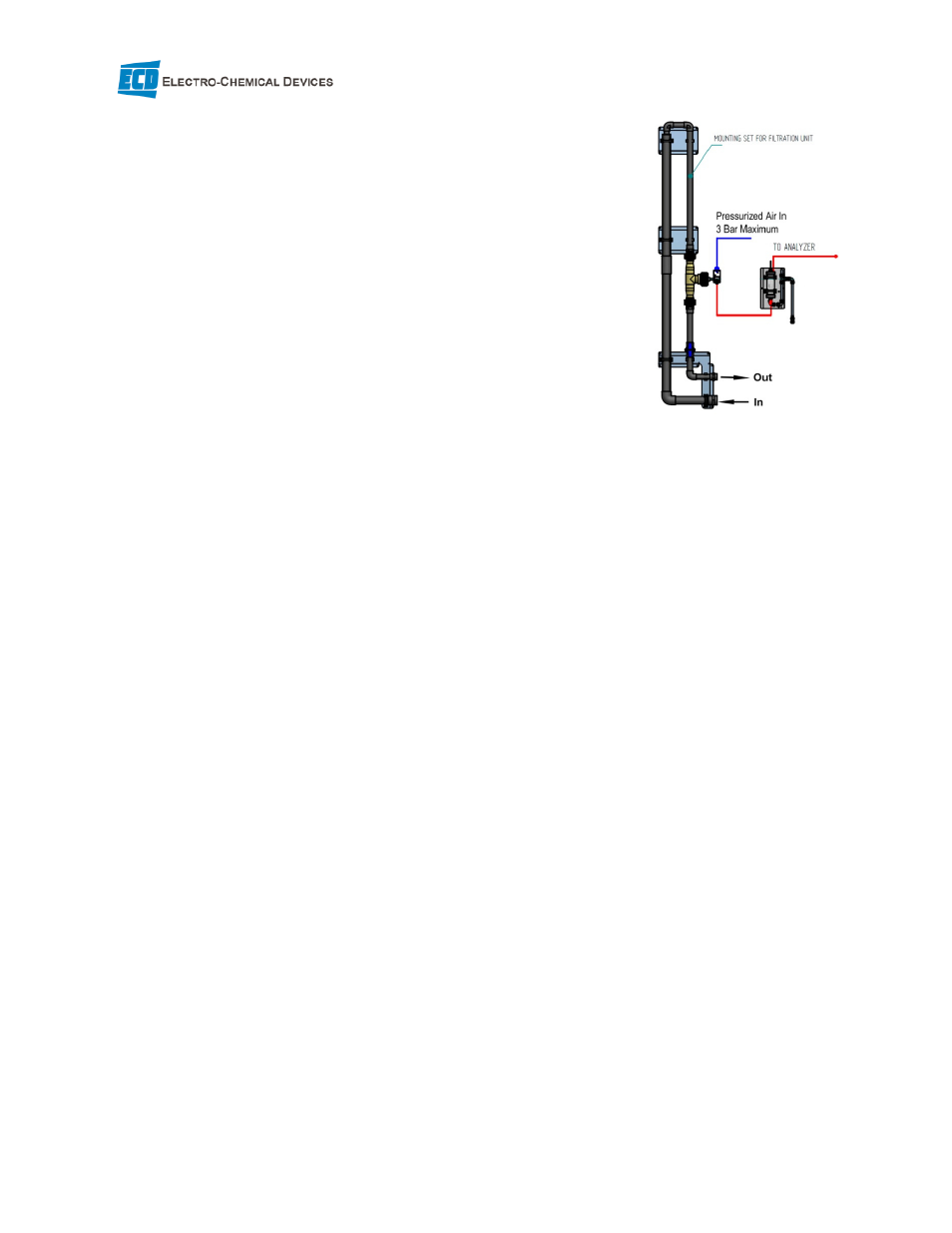
2.4 Pressurized Air Connection
The SF100 uses a 6 mm flexible tubing Quick Connect fitting for the air supply connection. The air supply
should be filtered and oil free to minimized sample contamination. A pressure regulator should be
installed for easy adjustment of the required blow back pressure, 7-10 psi above the water sample line
pressure.
The solenoid valve periodically actuates allowing compressed air to flow through the N.C. path of the
valve in the opposite direction of the filtered sample flow. The air flushes all particles from the filter.