7adjustments – Drake VM2551A Agile Modulator – 550 MHz User Manual
Page 7
7
Adjustments
ADJUSTMENTS
VIDEO LEVEL:
With the intended signal source connected and a representative video program
present, turn the VIDEO LEVEL ADJUST control clockwise until the Video Overmod-
ulation light just flashes, then back off slightly. Alternatively, while watching the
picture on a good TV monitor, adjust the control to the highest (clockwise) level
that does NOT cause the highlights (white portions of the picture) to become
“washed out”.
AUDIO LEVEL:
Turn the AUDIO LEVEL ADJUST control clockwise until the Audio Overmodulation
light just flashes slightly on the loudest peaks of the audio program material.
OUTPUT LEVEL:
The OUTPUT LEVEL is adjusted by pressing the UP or DN buttons when in the
OUTPUT LEVEL display mode. The LED display will blink indicating a transition
state. The output level is not changed until the ENTER button is pressed. If the
ENTER button is NOT pressed, the display will return to its resting state after 30
seconds. Pressing and holding the UP or DN button will allow for faster scrolling.
The level increments in 0.2 dB steps. Output level accuracy is typically +/- 1 dB of
display, +/- 2 dB worst case.
A/V CARRIER RATIO: To adjust the aural-to-visual carrier ratio, tune the RF indicator device to the aural
carrier frequency and adjust the AURAL CARRIER control to obtain the desired
aural carrier level. Recommended ratio is -15 dB.
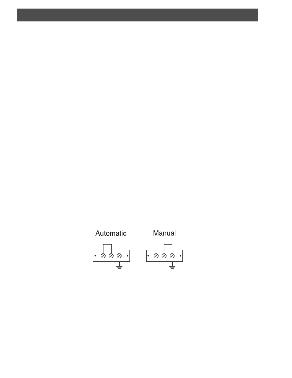
EAS / ALT IF
AUTOMATIC: Connect a jumper to the terminal strip auto position. EAS will switch on when a
+30 dBmV EAS IF signal is detected.
MANUAL:
EAS is active with a ground connection on the manual position of the terminal
strip.